You can test a knock sensor by checking its wiring, connector, resistance, and scan-tool data against your vehicle’s service specifications.
For drivers and DIY mechanics in the United States, learning how to test a knock sensor can help separate a failed sensor from a wiring problem or another engine issue. A knock sensor detects vibration associated with abnormal combustion and sends a signal to the engine control module so the module can adjust ignition timing.
The exact test depends on the vehicle, engine, sensor design, connector, and manufacturer specifications. Some factory procedures call for checking resistance or isolation between terminals, while others rely heavily on scan-tool data and circuit tests. For that reason, do not use one universal resistance number for every vehicle. Use the service information for the exact year, make, model, and engine before deciding that a sensor has failed.
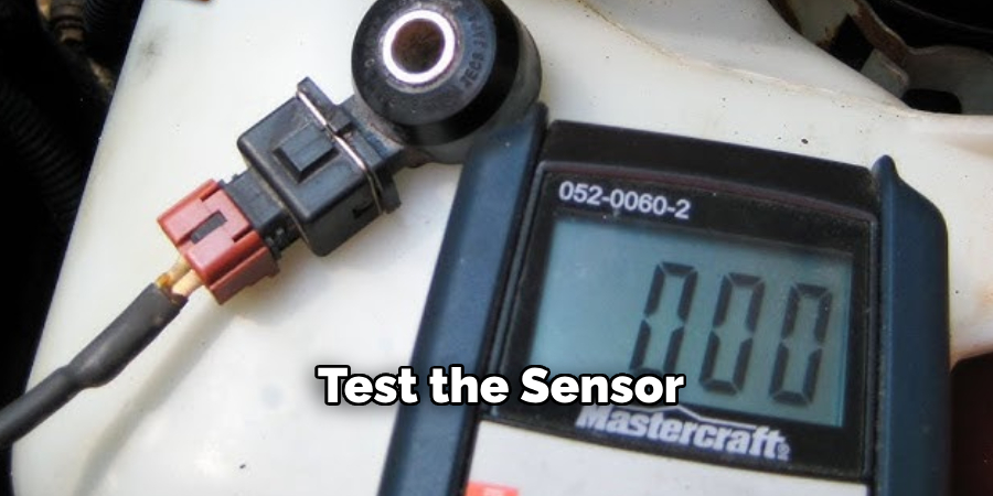
Source: youtube.com
What Is a Knock Sensor?
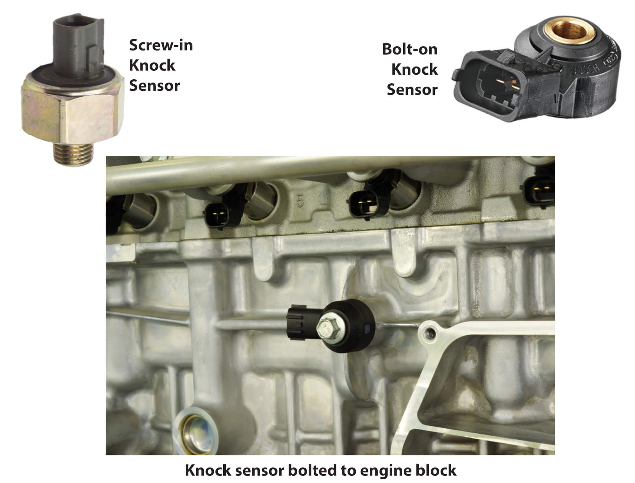
A knock sensor is an engine sensor that detects vibration associated with abnormal combustion, commonly called knock or detonation. The engine control module uses the sensor signal as part of its strategy for controlling ignition timing and protecting engine operation.
The sensor is commonly mounted directly to the engine block or another specified engine location. Because it detects vibration through its mounting point, the sensor and its contact surface must be installed correctly. Dirt, corrosion, incorrect mounting, damaged wiring, or an improperly secured sensor can affect the diagnosis.
A fault in the knock sensor circuit does not automatically mean the sensor itself is bad. A damaged connector, broken wire, poor ground, corrosion, or an engine-control problem can create similar diagnostic symptoms.
Source: apogeeweb.net
Sensor
The component detects engine vibration and produces an electrical signal that the engine control system can interpret.
Wiring
The harness carries the sensor signal between the sensor and the engine control module. An open or shorted circuit can imitate sensor failure.
Engine control module
The module processes the knock sensor signal along with other engine information and uses it in engine-control decisions.
What You Need Before Testing a Knock Sensor
Before testing the sensor, gather the tools and specifications needed for your particular vehicle. A digital multimeter is useful for basic electrical checks, but a scan tool and the manufacturer’s wiring diagram can make the diagnosis much more reliable.
Work with the engine off and allow hot components to cool before reaching into the engine compartment. Keep the vehicle securely parked, follow the manufacturer’s safety instructions, and disconnect electrical components only as directed by the service procedure.
Source: toolsweek.com
Digital multimeter
Use a quality meter capable of measuring resistance and electrical continuity. Select the correct measurement mode before testing.
Vehicle service information
Obtain the wiring diagram, connector pinout, sensor specifications, and test procedure for the exact engine.
Scan tool
A compatible scan tool can identify diagnostic trouble codes and may provide live data that helps confirm a sensor or circuit problem.
Basic hand tools
You may need tools to remove an engine cover or access panel and reach the knock sensor connector.
Why the Factory Specification Matters
Knock sensors do not all use the same electrical design or have the same specified readings. Factory procedures for different engines can call for different resistance checks, terminal combinations, or circuit limits. Some procedures specify an open circuit between particular terminals, while others specify a particular resistance range.
For example, published service procedures for certain Volkswagen engines specify an open-circuit reading between designated knock sensor terminals and a maximum wiring resistance of 1.5 ohms. Another Volkswagen application specifies a sensor resistance of about 5 megohms between particular terminals. These examples show why a generic resistance chart should not be used as a universal pass-or-fail test.
How to Test a Knock Sensor Step by Step
The safest approach is to diagnose the complete circuit instead of immediately replacing the sensor. Start with the vehicle’s diagnostic information, then inspect the sensor and wiring before performing electrical measurements.
The sequence below is a general diagnostic framework. The exact connector pins, resistance values, voltage checks, and access procedure must come from the service information for your vehicle.
Source: safetyfic.com
Step 1: Check for diagnostic trouble codes
Connect a compatible scan tool and record all relevant codes before clearing anything. Knock sensor circuit codes can help identify which sensor or circuit needs attention.
Step 2: Inspect the sensor
Locate the knock sensor and look for physical damage, loose mounting, contamination, corrosion, or signs of previous repairs.
Step 3: Inspect the connector
Check the connector for broken locks, pushed-back terminals, corrosion, moisture, damaged insulation, or poor terminal contact.
Step 4: Check the wiring
Follow the harness between the sensor and control module. Look for broken wires, rubbing, melted insulation, poor repairs, or shorts to power or ground.
Step 5: Disconnect the sensor as specified
With the ignition off, disconnect the knock sensor connector according to the service procedure. Do not probe terminals blindly because incorrect connections can damage components.
Step 6: Measure the sensor
Set the multimeter to the required resistance function and measure the specified terminal combination. Compare the reading with the exact factory specification rather than a generic online value.
Step 7: Test the wiring separately
If the sensor measurement is within specification, test the harness between the sensor connector and the engine control module using the wiring diagram. Check for excessive resistance, opens, and unintended continuity to power or ground as specified.
Step 8: Confirm the repair
After correcting a verified fault, reconnect everything correctly, clear codes only when appropriate, and follow the manufacturer’s procedure for verifying the repair and completing any required drive cycle.
Step 1: Scan for Trouble Codes First
A scan tool is often the fastest way to establish where to begin. Record the stored and pending diagnostic trouble codes and any freeze-frame information before clearing them. A code that points to a knock sensor circuit is useful evidence, but it does not by itself prove that the sensor has failed.
Look for other engine codes at the same time. A shared wiring issue, power problem, engine-control fault, or another condition can affect the knock sensor system.
Step 2: Locate and Inspect the Knock Sensor
Use the vehicle service information to identify the correct sensor. Some engines use one knock sensor, while others use multiple sensors. Access may require removing covers or other components.
Inspect the sensor and its mounting area before testing electrically. The sensor must be mounted as specified, and its contact surface may need to be clean and free of contamination. Do not assume that tightening the sensor as hard as possible is correct. Use the specified tightening procedure and torque.
Step 3: Test Knock Sensor Resistance With a Multimeter
Turn the ignition off and disconnect the sensor connector before performing a resistance test. Select the resistance function on the multimeter and identify the correct terminals from the wiring diagram or service procedure.
Place the meter probes on the specified terminals without forcing the probes into the connector. Record the reading and compare it with the factory specification. An open-circuit reading, a short circuit, or a resistance value outside the specified range can indicate a sensor problem, depending on the design.
Do not conclude that the sensor is good simply because the meter displays a number. A resistance test checks a particular electrical characteristic. It does not necessarily prove that the sensor produces the correct signal during real engine operation.
Step 4: Check the Knock Sensor Wiring
If the sensor passes its specified electrical test, move to the wiring. Use the vehicle’s wiring diagram to identify the correct terminals at the sensor and engine control module. Check for an open circuit, excessive resistance, and unintended shorts according to the manufacturer’s procedure.
A wiring test is especially important when the sensor itself measures within specification but the diagnostic code returns. Published factory procedures for some applications specify very low maximum harness resistance, illustrating why even a small amount of unwanted resistance can matter in a sensor circuit.
How to Interpret Your Knock Sensor Test Results
The result should be interpreted as part of the complete diagnostic procedure. A sensor reading that matches the specification supports the sensor’s electrical condition, but it does not eliminate wiring, mounting, connector, signal, or control-module problems.
Likewise, an abnormal reading does not always mean the sensor is the only problem. Verify the connector, test-point locations, meter operation, and factory specification before replacing a component.
Source: upgradedvehicle.com
Correct specified reading
The sensor’s tested circuit matches the manufacturer’s specification. Continue with wiring, signal, and code verification if the original problem remains.
Open circuit where resistance is expected
An open reading can indicate a broken sensor circuit or internal sensor fault, but verify the correct terminals and specification first.
Unexpected continuity or short
Continuity where the factory procedure calls for isolation can indicate an internal sensor fault or wiring problem.
Correct sensor but incorrect circuit reading
If the sensor passes but the harness fails, focus on wiring, terminals, connector condition, and the circuit between the sensor and control module.
Why a Good Resistance Reading Does Not Prove Everything
A knock sensor operates as part of a dynamic engine-control system. A static resistance measurement can detect certain electrical faults, but it cannot reproduce every condition that occurs while the engine is running.
If resistance is correct but a fault code persists, continue with the manufacturer’s signal and circuit tests. Depending on the vehicle, this may involve scan-tool data, waveform analysis, circuit voltage checks, or additional diagnostic procedures.
Common Symptoms of a Knock Sensor Problem
A failed knock sensor or knock sensor circuit can be associated with a check engine light, stored diagnostic trouble code, reduced engine performance, or changes in ignition timing strategy. However, these symptoms are not unique to the knock sensor.
Engine performance complaints can also result from ignition, fuel, mechanical, intake, exhaust, or other electronic faults. Testing is therefore more reliable than replacing the sensor based only on a symptom.
Source: autovehicleparts.com
Check engine light
The engine control module may illuminate the malfunction indicator lamp when it detects a fault in the knock sensor circuit or related system.
Stored diagnostic code
A diagnostic trouble code can identify a sensor or circuit condition that requires further testing.
Reduced performance
Some vehicles may alter engine-control strategies when the knock signal is missing or implausible, which can affect performance.
Poor fuel economy
Changes in engine-control strategy can sometimes be associated with fuel-economy changes, although many other faults can produce the same symptom.
Common Mistakes When Testing a Knock Sensor
The most common mistake is treating a generic online resistance value as universal. Knock sensor designs and factory procedures vary, so a number that applies to one engine may be wrong for another.
Another mistake is replacing the sensor without checking the connector and wiring. Because the engine control module depends on the complete circuit, a broken wire or poor terminal connection can produce a sensor-related code even when the sensor itself is functional.
Source: ricksfreeautorepairadvice.com
Using the wrong resistance specification
Always use specifications for the exact year, make, model, engine, and sensor configuration.
Testing with the sensor connected when the procedure requires disconnection
Follow the specified test configuration. Measuring through connected control electronics can produce misleading results.
Probing the wrong terminals
Confirm the connector pinout before placing meter probes on the sensor.
Ignoring mounting condition
The sensor’s mounting surface and specified installation procedure can affect its ability to detect engine vibration.
Replacing the sensor before testing the circuit
A new sensor will not fix a broken wire, corroded connector, incorrect installation, or control-module problem.
Clearing codes too early
Record diagnostic codes and freeze-frame information before clearing them because that information can help establish the original fault.
When You Should Stop DIY Testing
Stop and seek professional service if accessing the sensor requires major disassembly, the wiring diagram is unavailable, the sensor is difficult to reach safely, or the diagnosis requires procedures you cannot perform confidently.
Professional diagnosis is also appropriate when a replacement sensor does not correct the fault, multiple engine-control codes are present, or the vehicle has drivability problems that could indicate a separate mechanical or electrical issue.
Source: pinterest.com
Limited access
Do not remove components or work around hot, moving, or pressurized systems without the correct procedure and equipment.
Unclear specifications
Do not guess at a resistance value, terminal assignment, voltage, or tightening torque.
Persistent fault
If the code returns after a verified repair, continue diagnosis instead of repeatedly replacing parts.
Mechanical concerns
Unusual engine noise, severe performance problems, overheating, or other major symptoms may require a broader engine diagnosis.
Frequently Asked Questions
Q
Can you test a knock sensor with a multimeter?
Yes, a multimeter can be used for certain knock sensor electrical tests. Depending on the vehicle, the factory procedure may require resistance or isolation checks between specific terminals.
A multimeter cannot replace every diagnostic procedure. If the sensor passes a static electrical test but the fault remains, follow the vehicle-specific signal and circuit tests.
Q
What resistance should a knock sensor have?
There is no single resistance value that applies to every knock sensor. The correct value depends on the sensor design and vehicle.
For example, some published factory procedures specify an open-circuit condition between certain terminals, while another application specifies approximately 5 megohms between a particular pair. Always use the specification for the exact engine being tested.
Q
How do I know if my knock sensor is bad?
A knock sensor may be faulty when its electrical test fails the manufacturer’s specification, its connector or body is damaged, or a complete diagnostic procedure confirms that the sensor is responsible for the fault.
A check engine light or knock sensor trouble code alone does not prove the sensor has failed. Wiring, connectors, installation, and control-module issues can produce related faults.
Q
Can a bad knock sensor cause a check engine light?
Yes. A vehicle may illuminate the check engine light when its engine control module detects a problem with the knock sensor or its circuit.
The stored diagnostic trouble code should be used as a starting point for testing rather than as automatic proof that the sensor needs replacement.
Q
Can I test a knock sensor without removing it?
Some preliminary checks can be performed without removing the sensor, including scanning for codes, inspecting the connector and wiring, and checking accessible circuit information.
A resistance test commonly requires disconnecting the sensor from its harness. Other vehicles may require additional signal or scan-tool tests while the sensor remains installed.
Q
Does a knock sensor need to be tightened to a specific torque?
Yes, when the manufacturer specifies a tightening torque, use that specification. The sensor detects vibration through its mounting, so incorrect installation can affect its operation.
Do not apply a generic torque value to every vehicle. The correct specification belongs to the exact sensor and engine application.
✦ Wrapping Up
Conclusion
Learning how to test a knock sensor starts with diagnosis, not parts replacement. Scan the vehicle, inspect the sensor and connector, check the wiring, and then perform the electrical tests specified for the exact engine.
A multimeter can identify important sensor and circuit faults, but a normal reading does not automatically prove that the complete knock detection system is working. When the results remain unclear, use the manufacturer’s service procedure or have a qualified technician complete the diagnosis.
💡 Key Takeaway
Before replacing a knock sensor, record the trouble codes, verify the correct sensor and connector, inspect the wiring, and compare every electrical measurement with the exact factory specification for your vehicle.
Ethan Brooks is an automotive writer at Auto News 7, covering car news, vehicle maintenance, new model updates, recalls, and practical buying guides. He focuses on clear, useful information that helps drivers understand their vehicles and make better ownership decisions.
Learn how to diagnose a bad crankshaft position sensor with symptoms, testing methods, scan tool checks, multimeter tests, and practical troubleshooting steps.
Learn how to replace crankshaft position sensor Ford F150 models safely, including tools, access points, removal steps, installation tips, and troubleshooting.
Learn how to replace camshaft position sensor Pontiac G6 models with this detailed step-by-step guide. Discover tools, symptoms, sensor location, installation tips, and troubleshooting advice.
Learn whether camshaft and crankshaft sensors are interchangeable, how they differ, common symptoms of failure, compatibility concerns, and the correct replacement approach.