You can test a knock sensor with a multimeter by checking its specified resistance, wiring, and signal output.
For U.S. drivers working on a car or truck at home, learning how to test a knock sensor with multimeter can help separate a failed sensor from a wiring or connector problem. A digital multimeter can perform several useful checks, but the correct test depends on the vehicle because knock sensor designs and factory specifications vary.
A knock sensor detects vibration associated with engine knock and sends an electrical signal to the engine control module. Some sensors can be evaluated with a resistance test, while others require a specific voltage or circuit test from the vehicle service information. Factory procedures differ enough that there is no single resistance value that is correct for every vehicle.
The safest approach is to identify the exact sensor and obtain the factory specification before interpreting a measurement. Turn the ignition off before disconnecting the sensor for resistance testing, keep test leads away from moving or hot engine parts, and never assume a sensor is defective simply because one generic resistance value does not match your reading.
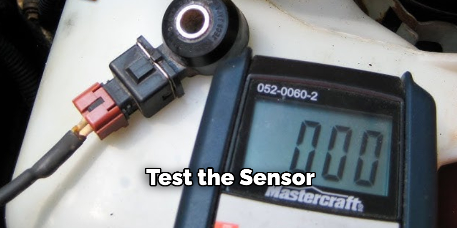
Source: storage.googleapis.com
What Does a Knock Sensor Do?
A knock sensor detects vibration caused by abnormal combustion and converts that mechanical vibration into an electrical signal. The engine control module uses this information to adjust engine operation when knock is detected.
Most automotive knock sensors use a piezoelectric sensing element. The element responds to vibration by producing an electrical signal. Because the signal can be small, the sensor circuit and mounting conditions matter during diagnosis.
A faulty sensor is only one possible cause of a knock-related trouble code. Damaged wiring, poor connections, shorts, incorrect mounting, contamination, or a problem elsewhere in the engine can create similar symptoms.
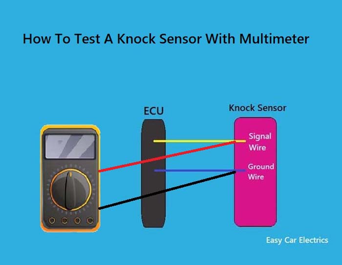
Source: watelectronics.com
Knock sensor
The vibration-sensitive component mounted to the engine block or another specified location.
Engine control module
The computer that receives the knock sensor signal and uses it as part of engine-control decisions.
Knock sensor circuit
The sensor, connector, wiring, reference or bias circuit where applicable, and the control-module connection.
Why Testing the Sensor Alone Is Not Always Enough
A resistance measurement only evaluates the electrical condition that the particular test is designed to check. It does not automatically prove that the sensor produces the correct signal during engine operation.
Vehicle service information may instead specify a resistance-to-ground test, a terminal-to-terminal test, a bias-voltage test, a signal test, or a scan-tool procedure. Some systems should not be judged by a generic resistance test at all.
Sensor fault
The sensing element or internal electrical path may be damaged.
Harness fault
An open wire, short, damaged insulation, poor ground, or corroded connector can interrupt the signal.
Mechanical fault
Incorrect mounting, contamination, or improper tightening can affect sensor operation on vehicles where mounting conditions are specified.
What You Need Before Testing a Knock Sensor
Before testing, identify the exact year, make, model, engine, and sensor location. The required test and specification can change between engines, even within the same model year. Use the vehicle service manual or manufacturer repair information to find the connector pinout and specified test value.
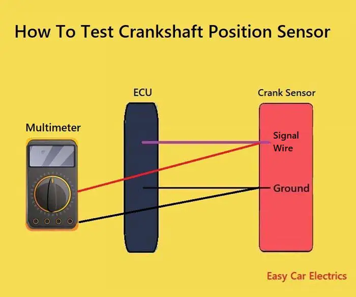
A quality digital multimeter is the main tool. A vehicle wiring diagram is also valuable because the connector may contain a signal circuit, a return circuit, shielding, or a bias circuit depending on the design.
If the vehicle has a stored diagnostic trouble code, record the code and freeze-frame information before clearing anything. Codes such as P0327, P0328, P0332, and P0333 can point toward knock sensor circuit problems, but the code alone does not prove that the sensor itself has failed.
Source: safetyfic.com
Digital multimeter
Use a high-impedance meter suitable for automotive electrical diagnosis.
Vehicle-specific specification
Find the exact resistance, voltage, pin assignment, and testing conditions for the vehicle.
Wiring diagram
Use it to identify sensor terminals and trace the circuit between the sensor and engine control module.
Basic safety equipment
Use eye protection and keep clothing, hands, and test leads away from belts, fans, pulleys, exhaust components, and other moving or hot parts.
Safety Checks Before Using the Multimeter
For a resistance test, switch the ignition off and disconnect the sensor connector before placing the multimeter in resistance mode. Never measure resistance on a powered circuit because the meter can be damaged and the reading can be meaningless.
If a voltage test requires the ignition on or the engine running, follow the vehicle-specific procedure. Keep the vehicle secured according to the manufacturer’s instructions and avoid placing your hands near moving components.
Do not deliberately create engine knock to test a sensor. A controlled electrical or signal test is safer than trying to reproduce destructive combustion conditions.
Power off for resistance
Disconnect the sensor before using the ohms function unless the service procedure specifically says otherwise.
Avoid short circuits
Do not allow a probe to bridge adjacent terminals in a connector.
Protect the connector
Use suitable back-probing methods rather than damaging seals or terminals with oversized probes.
How to Test a Knock Sensor With a Multimeter
The most useful starting point is a visual inspection followed by the exact electrical test specified for your vehicle. Do not begin by applying a generic resistance number to every knock sensor.
The following sequence gives you a practical diagnostic framework. The exact terminal numbers, resistance range, voltage specification, and test conditions must come from the vehicle-specific service information.
Source: electrozlab.com
Step 1: Locate the sensor
Find the knock sensor and identify its connector, mounting point, and wiring.
Step 2: Inspect the wiring
Look for broken insulation, corrosion, loose terminals, oil contamination, heat damage, or wiring pulled tightly against another component.
Step 3: Disconnect the sensor
Switch the ignition off and disconnect the sensor connector before performing an unpowered resistance test.
Step 4: Select resistance mode
Set the multimeter to ohms and choose a range capable of displaying the specified resistance.
Step 5: Measure the specified terminals
Place the probes across the exact terminals identified by the service procedure.
Step 6: Compare the reading
Compare the measured value with the manufacturer’s specification, including any stated temperature condition.
Step 7: Test the harness if required
Check continuity and shorts in the wiring according to the circuit diagram rather than assuming a failed sensor.
Step 8: Perform a signal test when specified
Some systems require a voltage, scan-tool, or oscilloscope test to confirm sensor operation under vibration.
Step 1: Inspect the Knock Sensor and Connector
Start with the engine off and cool enough to inspect safely. Look at the sensor body, mounting area, connector, and harness. Check for visible damage, corrosion, broken insulation, loose terminals, or contamination.
Pay attention to the mounting area because some manufacturers specify a particular mounting surface and tightening torque. A sensor that is electrically sound can still produce incorrect results if its installation does not meet the vehicle specification.
Check the sensor body
Look for cracks, physical damage, or signs that the sensor has been struck or dropped.
Check the connector
Look for bent pins, corrosion, moisture, damaged locks, or terminals that do not grip correctly.
Check the harness
Look for chafing, breaks, melted insulation, and evidence of contact with hot or moving engine components.
Step 2: Perform the Resistance Test
With the sensor disconnected, place the multimeter probes on the terminals specified by the service information. Some factory procedures measure resistance between two sensor terminals. Others measure a terminal to the sensor body or ground.
The expected value varies substantially by sensor and vehicle. For example, published service procedures include sensors specified in the hundreds of kilohms, sensors specified at several megohms, and other designs with very different requirements. Therefore, a generic value such as 500 ohms, 500 kilohms, or infinite resistance should never be treated as a universal standard.
An open reading such as OL can indicate a failed sensor when the service manual calls for a finite resistance. Conversely, an OL reading may be normal on a sensor or terminal combination where the manufacturer specifies an open circuit. The specification determines the result.
Finite reading outside specification
The sensor may have an internal fault if the measured value is outside the manufacturer’s specified range.
OL when a finite value is specified
This can indicate an open internal circuit and may support sensor replacement.
Near-zero reading when an open circuit is specified
This can indicate an unintended short between the tested points.
Step 3: Test the Knock Sensor Wiring
If the sensor measurement is within specification, move to the harness. A sensor can test normally while its signal never reaches the engine control module because of an open wire, short, damaged terminal, or connector problem.
The usual harness checks include continuity between the sensor connector and the control-module connector and checks for unintended continuity to ground or power. The exact procedure depends on the circuit design.
Disconnect the appropriate connectors before performing resistance or continuity checks on the harness. Compare your readings with the service manual rather than assuming that every circuit should show zero ohms or infinite resistance.
Open circuit
A broken conductor can prevent the sensor signal from reaching the control module.
Short to ground
An unintended connection to ground can alter or eliminate the expected signal.
Short to power
An unintended connection to a power source can create an incorrect circuit voltage and trigger a fault.
How to Test Knock Sensor Voltage and Signal
A voltage test is useful only when the vehicle’s circuit design and service procedure call for it. Some knock sensor systems use a bias or reference voltage from the control module, while others are tested primarily by measuring the sensor’s generated signal.
Do not assume that every knock sensor should show 5 volts. Some vehicles do use a bias voltage, but the expected value and measurement points depend on the circuit. A correct voltage at the connector can help prove that part of the circuit is present, but it does not by itself prove that the sensor responds correctly to vibration.
For a dynamic signal test, the manufacturer may specify an oscilloscope or another diagnostic method. A multimeter may sometimes show a changing voltage when the sensor experiences vibration, but a meter cannot display waveform details as accurately as an oscilloscope.
Source: storage.googleapis.com
When a Voltage Test Makes Sense
Use a voltage test when the service information provides a voltage specification and identifies the correct terminals and ignition condition. Some systems can be checked with the sensor disconnected, while others require a connected circuit and careful back-probing.
If the specified bias or reference voltage is missing, investigate the wiring, power supply, control module, connector, and related circuit before replacing the sensor. If the voltage is correct but the sensor signal is wrong, continue with the manufacturer’s sensor test.
Correct reference voltage
This can indicate that the control-module side of the circuit is supplying the expected electrical condition.
No reference voltage
Investigate the circuit before condemning the sensor.
Signal does not respond
A failed sensor, wiring problem, incorrect mounting, or another engine-control issue may be involved.
Why You Should Not Hit the Sensor Directly
Some diagnostic procedures use controlled vibration near the sensor to observe a signal. That does not mean you should strike the knock sensor itself with a hammer or other hard object.
If a dynamic test is required, follow the exact factory procedure. The goal is to verify the circuit’s response without damaging the sensor, engine, wiring, or surrounding components.
Use controlled vibration
Only perform a vibration test when the procedure supports it and follow the specified method.
Do not create real detonation
Testing should not involve intentionally causing damaging engine knock.
How to Interpret Your Multimeter Reading
The most important rule is to compare the measurement with the correct factory specification. A multimeter reading has meaning only when you know which terminals were tested, whether the sensor was disconnected, what temperature condition applies, and what value the manufacturer expects.
A simple decision table can help organize the diagnosis. It should not replace the vehicle-specific service procedure.
Source: pinterest.com
Reading matches specification
The tested electrical property is within the specified range. Continue testing the circuit or signal if a fault remains.
Reading is outside specification
The sensor or tested circuit may be faulty. Repeat the measurement carefully and verify the correct specification before replacing anything.
OL or infinite resistance
This can mean an open circuit, but whether it indicates failure depends on the exact terminals and factory specification.
Near-zero resistance
This may indicate a short when the tested circuit is supposed to be open or have substantial resistance.
Example of Why Factory Specifications Matter
One published vehicle procedure specifies a knock sensor resistance of approximately 532 to 588 kilohms at 20 degrees Celsius, while another service procedure specifies a sensor resistance of 4,870 kilohms. Other procedures call for an open-circuit reading between particular terminals.
These differences show why copying a resistance number from another vehicle can lead to a wrong diagnosis. The correct specification belongs to the exact sensor and engine being tested.
Vehicle A
A factory specification may call for a finite resistance in a particular range.
Vehicle B
Another sensor may have a much higher specified resistance or a different terminal test.
Vehicle C
A manufacturer may instruct technicians to verify an open circuit instead of a finite resistance.
Common Mistakes When Testing a Knock Sensor
Many incorrect knock sensor diagnoses come from using a generic test instead of the manufacturer’s procedure. A multimeter is useful, but it cannot compensate for an incorrect pinout, wrong meter mode, or unsuitable test condition.
Take your time when interpreting an unexpected reading. Repeat the measurement, confirm the meter works correctly, verify the connector terminals, and check the service specification before buying a replacement sensor.
Source: youtube.com
Using the wrong resistance specification
Knock sensor resistance varies by design, so a value from another vehicle may be irrelevant.
Testing a powered circuit in resistance mode
Resistance measurements should normally be made on an unpowered, disconnected circuit unless the service procedure specifically states otherwise.
Assuming every sensor should read 5 volts
Some circuits use a bias voltage, but the expected value and test method are vehicle-specific.
Replacing the sensor without checking the harness
An open, short, corroded connector, or damaged terminal can produce the same fault symptoms.
Using a test light on a sensitive circuit
A digital multimeter is generally more appropriate for high-impedance electronic circuits because it places less electrical load on the circuit.
Striking the sensor directly
A sensor should not be hit with a hard tool simply to see whether the meter changes.
When a Multimeter Test Is Not Enough
A multimeter may establish that a sensor has an obvious open or short, but it may not prove that the sensor produces the correct waveform during actual engine operation. If the resistance and wiring checks pass while the fault remains, the next step may be a scan-tool data check or oscilloscope test.
Professional diagnosis may also be appropriate when access to the sensor requires significant disassembly, when the wiring enters a difficult-to-access engine harness, or when the diagnostic procedure requires specialized equipment.
Use a scan tool
A scan tool can help confirm diagnostic codes and observe relevant engine data when supported by the vehicle.
Use an oscilloscope
An oscilloscope can display signal changes and waveform characteristics that a basic multimeter may not show.
Use professional diagnosis
Seek qualified automotive service when the required procedure exceeds your tools, access, or experience.
What to Do If the Knock Sensor Tests Good
If the sensor meets its resistance specification and the wiring checks are normal, do not automatically replace the sensor. Continue with the diagnostic procedure for the specific fault code or symptom.
Check connector condition, mounting requirements, circuit bias or reference voltage where applicable, and the sensor signal under the conditions specified by the manufacturer. A persistent code can originate from a circuit or engine condition rather than the sensor itself.
If the diagnostic procedure identifies no electrical fault, the next step may involve checking related engine-control data, mechanical conditions, or other causes that can produce abnormal combustion or a misleading knock-related symptom.
Source: youtube.com
Recheck the connector
A terminal that looks clean can still have poor contact or an incorrect terminal fit.
Verify mounting
Confirm the sensor mounting surface and tightening specification when the manufacturer provides them.
Review the complete diagnostic code procedure
Follow the manufacturer’s diagnostic tree instead of treating the sensor resistance test as the final answer.
When to Stop DIY Testing
Stop and obtain qualified help if testing requires working around moving engine components that you cannot safely access, if the vehicle must be raised and you do not have appropriate support equipment, or if you are unsure about the electrical circuit.
A knock sensor fault can sometimes accompany a genuine engine-control or combustion problem. Driving for an extended period with unresolved engine knocking or a persistent fault should not be treated as a simple sensor replacement issue without diagnosis.
Safety first
Do not continue a test when the procedure creates an unsafe working condition.
Use qualified service
A professional technician can use manufacturer procedures, scan tools, oscilloscopes, and other diagnostic equipment when needed.
Frequently Asked Questions
Q
What should a knock sensor read on a multimeter?
There is no single resistance value that applies to every knock sensor. Depending on the vehicle, the factory procedure may specify a particular resistance range, a very high resistance, or an open circuit between specific terminals.
Use the exact specification for your year, make, model, engine, and sensor. Do not diagnose a sensor from a generic resistance number found for another vehicle.
Q
Can you test a knock sensor with a multimeter?
Yes, a multimeter can perform useful knock sensor tests on many vehicles. These may include resistance, continuity, circuit voltage, or signal checks, depending on the sensor and manufacturer procedure.
A multimeter test does not always prove complete sensor operation. Some systems require a scan tool or oscilloscope for a more complete signal diagnosis.
Q
Should a knock sensor have continuity?
It depends on which terminals you test and what the manufacturer specifies. Some knock sensor procedures expect a finite resistance between terminals, while other procedures expect an open circuit between particular terminals or between a terminal and the sensor body.
Always identify the correct terminals before interpreting continuity. A continuity beep by itself does not mean the sensor is good.
Q
How do I know if my knock sensor is bad?
A sensor that fails its manufacturer-specified resistance or signal test may be defective. Physical damage, an internal short, or an open circuit can also support a sensor-failure diagnosis when the service procedure identifies those conditions as faults.
Before replacing the sensor, check the connector and wiring because an open circuit, short, or poor connection can create similar symptoms.
Q
Can a bad knock sensor cause a check engine light?
Yes. The engine control module can set diagnostic trouble codes when it detects an abnormal knock sensor circuit or signal. Common code families include P0327, P0328, P0332, and P0333, although the exact code and diagnostic meaning depend on the vehicle.
A check engine light with a knock-related code does not automatically mean the sensor itself needs replacement. The associated diagnostic procedure should be followed.
Q
Can I test a knock sensor without removing it?
Some circuit and voltage tests can be performed with the sensor installed. Other resistance tests require the sensor connector to be disconnected, and some manufacturer procedures require additional access or component removal.
Follow the vehicle-specific test instructions and never place an ohmmeter across a powered circuit.
✦ Wrapping Up
Conclusion
Learning how to test a knock sensor with multimeter starts with the correct vehicle-specific specification. A digital multimeter can help identify an open circuit, short, incorrect resistance, wiring problem, or missing circuit voltage, but the exact test depends on the knock sensor design.
Start with a visual inspection, disconnect the sensor before resistance testing, measure the correct terminals, and compare every result with the manufacturer’s specification. If the basic test passes, continue with wiring and signal diagnosis instead of replacing the sensor automatically.
When a knock-related fault remains after basic electrical checks, a scan tool, oscilloscope, wiring diagram, or professional diagnostic procedure may be necessary. That approach reduces the risk of replacing a good sensor when the real problem is in the harness, connector, mounting, or another part of the engine-control system.
💡 Key Takeaway
Before replacing a knock sensor, record the fault code, identify the exact factory test specification, inspect the connector and wiring, perform the correct multimeter test, and verify the result before making a repair.
Ethan Brooks is an automotive writer at Auto News 7, covering car news, vehicle maintenance, new model updates, recalls, and practical buying guides. He focuses on clear, useful information that helps drivers understand their vehicles and make better ownership decisions.
Learn how to test camshaft position sensor wiring with a multimeter. Follow a safe step-by-step process to check power, ground, signal circuits, and common wiring faults.
Learn how many ohms a camshaft sensor should have, why resistance varies by sensor type, and how to test a camshaft position sensor accurately with a multimeter.