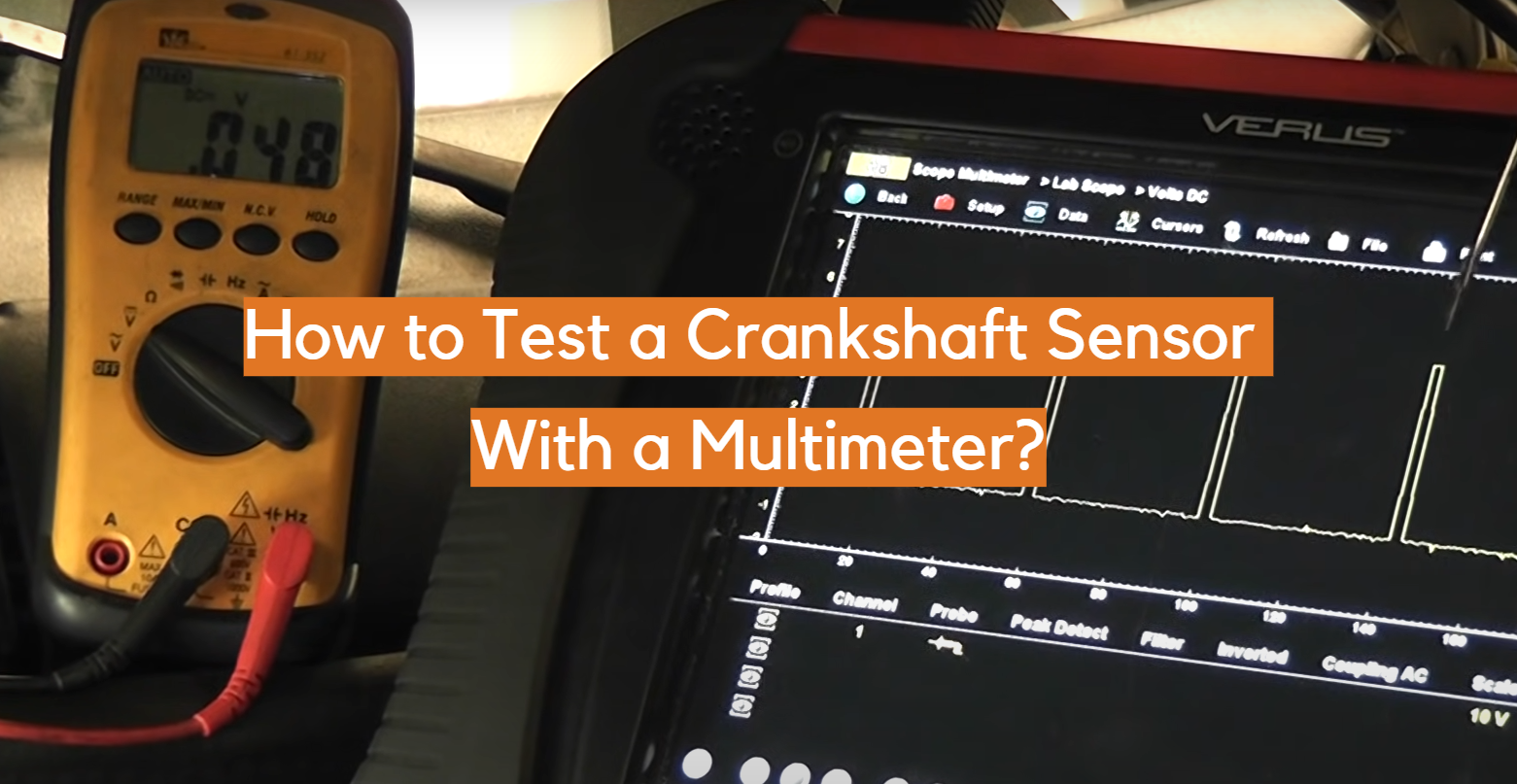
To test a crankshaft position sensor with a multimeter, first identify whether it is an inductive two-wire sensor or an active Hall-effect sensor. Test an inductive sensor for its specified resistance and AC output while cranking; test a Hall-effect sensor by checking its power supply, ground, and switching signal.
For U.S. drivers diagnosing a hard-starting, stalling, or no-start vehicle at home, a digital multimeter can provide useful evidence about the crankshaft position sensor before parts are replaced. The important detail is that there is no single multimeter procedure or universal voltage and resistance specification for every American-market car, pickup, or SUV. Ford, Chevrolet, Toyota, Honda, Jeep, Nissan, Subaru, Hyundai, and other manufacturers use different sensor designs and circuit strategies, so the factory service information for the exact year, make, model, and engine should be your reference for terminal identification and acceptable readings.
The crankshaft position sensor, commonly abbreviated CKP, tells the powertrain control module where the crankshaft is in its rotation and how fast it is turning. The computer uses this information when controlling functions such as ignition and fuel injection. A failed CKP sensor can contribute to a crank-no-start condition, intermittent stalling, misfires, extended cranking, or crankshaft-position-related diagnostic trouble codes, but those symptoms do not prove the sensor itself is defective. Damaged wiring, poor connector contact, low battery voltage during cranking, an excessive sensor air gap, or a damaged reluctor wheel can produce similar results.
A multimeter is therefore most useful when it is used as part of a diagnosis rather than as a simple pass-or-fail sensor checker. Start with a visual inspection, identify the sensor type, obtain the correct wiring information, and then perform the electrical tests that apply to that design.
Source: harleydavidsonblog.com
What You Need Before Testing a Crankshaft Position Sensor
Before touching the sensor connector, gather the information and tools needed to test the circuit without damaging it. At minimum, you need a digital multimeter that can measure DC voltage, AC voltage, and resistance. Back-probe leads or thin automotive test probes are preferable to forcing standard multimeter probes into connector terminals.
You also need a wiring diagram or reliable service information for the specific vehicle. This tells you how many wires the sensor has, which terminal is power, ground, or signal, and what readings the manufacturer expects. Wire color alone is not a dependable way to identify a circuit because colors and pin assignments vary between models.
Allow hot engine and exhaust components to cool before reaching near the sensor. If the sensor is accessible only from underneath the vehicle, support the vehicle with properly rated jack stands on a stable surface. Never rely on a hydraulic jack alone.
Live electrical tests may require the ignition to be on or the engine to be cranked. Keep hands, clothing, test leads, and tools away from belts, pulleys, fans, and other rotating parts. Remember that electric cooling fans can sometimes operate unexpectedly.
Source: electronicshacks.com
Digital multimeter
Use a meter capable of measuring resistance, low AC voltage, and DC voltage.
Back-probe leads
These allow measurements with the connector attached without spreading or damaging its terminals.
Vehicle service information
Use the correct wiring diagram, pin identification, resistance specification, voltage specification, and test procedure for your vehicle.
Basic safety equipment
Wear eye protection and use proper vehicle supports if access underneath the vehicle is required.
Locate and Inspect the CKP Sensor First
Crankshaft position sensor locations vary significantly. Depending on the engine, the sensor may be near the crankshaft pulley, timing cover, engine block, oil pan area, transmission bell housing, flywheel, or flexplate. Consult service information rather than removing components based on a generic location.
Inspect the harness before performing electrical measurements. Look for rubbed insulation, melted wiring, oil or coolant contamination, corrosion, backed-out terminals, broken connector locks, and wiring routed too close to the exhaust. Also make sure the sensor is securely mounted.
A wiring or connector defect should be corrected before condemning the sensor. A good sensor cannot deliver a usable signal if its electrical connection to the powertrain control module is compromised.
Check connector condition
Look for moisture, corrosion, loose terminals, damaged locks, or contamination.
Inspect the harness
Pay particular attention to areas exposed to engine heat, vibration, oil, road debris, or sharp brackets.
Inspect sensor mounting
A loose sensor or incorrect sensor-to-target clearance can affect signal strength.
Identify Whether You Have a 2-Wire or 3-Wire Crankshaft Sensor
Correctly identifying the sensor design is the most important step before testing. The two common designs are variable-reluctance, also called inductive or magnetic sensors, and active sensors such as Hall-effect sensors.
A conventional inductive CKP sensor is commonly a two-wire device. It contains a coil and magnet and generates its own alternating voltage as the teeth of a reluctor or tone wheel move past the sensor. Because it produces an AC signal, both resistance and dynamic AC-output measurements may be useful when the manufacturer specifies them.
A Hall-effect sensor is commonly a three-wire device consisting of a power supply, ground, and signal circuit. It requires external electrical power and produces a digital switching signal. Resistance testing across an active sensor is generally not the correct diagnostic approach unless the vehicle manufacturer specifically provides such a test.
Wire count is a useful clue, not an absolute identification method. Some automotive sensor designs do not follow the simple two-wire-versus-three-wire pattern. Verify the type using the wiring diagram before connecting the meter.
Source: easycarelectrics.com
Two-wire inductive sensor
Usually generates its own AC voltage and may have a manufacturer-specified coil resistance.
Three-wire active sensor
Usually requires power and ground and sends a switching signal back to the engine computer.
Do not guess from wire colors
Use the connector pinout for the exact vehicle rather than assuming a particular wire is power or ground.
Why Sensor Type Changes the Test
An ohmmeter works by applying a small electrical test current to the component being measured. That is appropriate for checking the coil in many passive inductive sensors. An active electronic sensor contains internal circuitry, however, so the correct diagnosis focuses on its operating power, ground quality, and output signal.
Using the wrong method can produce meaningless readings and may expose sensitive electronic circuits to an inappropriate test. When the sensor type is uncertain, stop and identify the circuit from service information before continuing.
How to Test a 2-Wire Crankshaft Position Sensor With a Multimeter
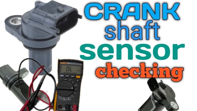
For a confirmed two-wire variable-reluctance sensor, begin with the sensor and ignition switched off. Disconnect the sensor from the vehicle harness before measuring its internal resistance. Set the multimeter to the ohms setting and place one probe on each sensor terminal.
Compare the displayed resistance directly with the specification in the service manual. Different CKP sensors can have substantially different winding resistance, so a generic range should not be used to approve or reject the sensor. An OL or infinite reading commonly indicates an open winding, while a reading extremely close to zero can indicate a shorted winding. A normal resistance reading only confirms that the winding is not obviously open or shorted; it does not prove that the sensor produces a correct signal while operating.
The more useful dynamic check is measuring the sensor’s AC output while the crankshaft is turning. Configure the test exactly as the manufacturer specifies. Depending on the circuit, this may involve testing directly at the disconnected sensor or back-probing the connected circuit.
Set the multimeter to AC volts, using a low-voltage range when the meter is not auto-ranging. Position the leads securely, keep them away from moving parts, and have an assistant crank the engine for several seconds. A variable-reluctance sensor should generate an AC voltage while the target wheel moves past it.
Compare the measured output with the manufacturer’s specification rather than expecting a universal number. Signal amplitude changes with sensor design, cranking speed, battery condition, sensor air gap, target-wheel condition, and meter response.
Source: carinterior.alibaba.com
Step 1
Confirm from service information that the sensor is an inductive or variable-reluctance type.
Step 2
Turn the ignition off and disconnect the sensor before performing a specified resistance test.
Step 3
Measure resistance across the correct sensor terminals and compare the result with the exact vehicle specification.
Step 4
Configure the circuit for the manufacturer’s dynamic output test and set the multimeter to AC voltage.
Step 5
Crank the engine while monitoring AC voltage, then compare the reading with the service specification.
What a Low or Missing AC Signal Can Mean
Little or no AC output does not automatically prove the sensor itself has failed. A weak battery or slow starter can reduce cranking speed and therefore reduce the voltage generated by a variable-reluctance sensor. Excessive clearance between the sensor and target wheel can have a similar effect.
Inspect for metallic debris on a magnetic sensor tip where applicable, physical damage to the sensor, incorrect installation, and problems with the reluctor wheel. A cracked, loose, shifted, or damaged target wheel can cause an abnormal signal even when the sensor is electrically healthy.
Low cranking speed
Test battery and starting-system condition if the engine is rotating unusually slowly.
Incorrect air gap
Verify sensor installation and the specified sensor-to-target clearance where it is adjustable or measurable.
Reluctor damage
Missing teeth, physical damage, or a shifted target can cause incorrect CKP information.
Sensor contamination
Metallic debris on some magnetic sensors can interfere with proper operation.
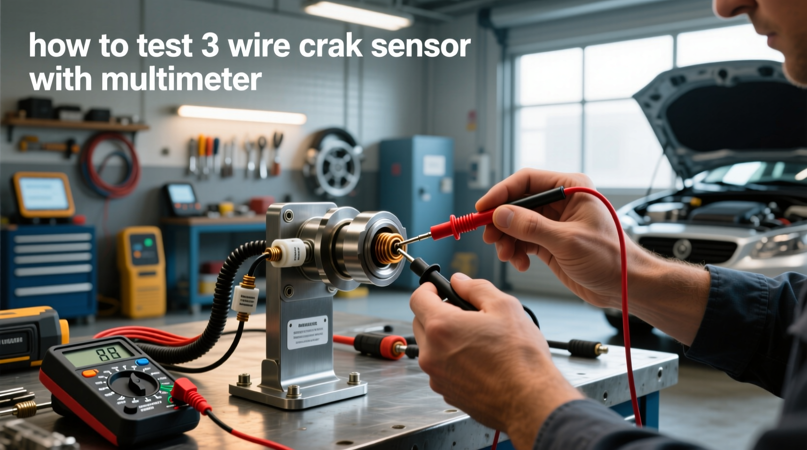
How to Test a 3-Wire Crankshaft Position Sensor With a Multimeter
A typical three-wire Hall-effect CKP sensor is tested as a powered circuit. Instead of measuring resistance across the sensor, identify its power, ground, and signal terminals from the wiring diagram and check each part of the circuit.
Start with the ignition state specified by the service procedure, often key on with the engine off for the initial supply-voltage check. Set the multimeter to DC volts. With the black meter lead connected to the specified reference point, back-probe the sensor’s supply circuit.
Many automotive Hall-effect sensors operate from a regulated reference supply such as 5 volts, while other designs can use different supply voltages. Treat the service-manual specification as authoritative. If the required supply is absent, investigate the power circuit before replacing the sensor.
Next verify the ground. A ground that shows continuity with the circuit unloaded may still have excessive resistance under operating conditions. When the manufacturer permits it, a voltage-drop test with the sensor operating provides a better indication of ground-circuit quality.
Finally, check the signal circuit with the sensor connected. Back-probe the correct signal terminal, set the meter to DC volts, and crank the engine. A Hall-effect CKP signal normally switches between low and high states as the target passes the sensor. A basic digital multimeter may display a rapidly changing value or an averaged voltage because it cannot show each individual pulse.
Source: pinterest.com
Step 1
Identify the power, ground, and signal terminals from the correct wiring diagram.
Step 2
Verify the specified supply voltage with the ignition in the required position.
Step 3
Verify the sensor ground and perform a voltage-drop test when the service procedure calls for one.
Step 4
Back-probe the signal circuit with the sensor connected.
Step 5
Crank the engine and watch for signal activity, then compare the result with the manufacturer’s diagnostic information.
How to Interpret a Hall-Effect Sensor Test
If the power supply is missing, the problem may be an open circuit, short circuit, shared reference-voltage fault, connector problem, or control-module issue rather than a failed CKP sensor. If power is correct but ground is poor, repair the ground circuit before evaluating the signal.
If power and ground meet specification but the signal shows no switching during cranking, inspect the signal circuit, connector terminals, sensor mounting, and target wheel before deciding the sensor is defective. A signal circuit shorted to voltage or ground can hold the reading at one level even when the sensor itself is capable of operating.
No supply voltage
Diagnose the supply or reference circuit instead of immediately replacing the CKP sensor.
Poor ground
Repair excessive resistance or voltage drop in the ground path before retesting.
Signal stuck high or low
Check both the sensor and the signal wiring for opens or shorts.
Using Frequency or Duty Cycle
Some digital multimeters can measure frequency or duty cycle. These functions may provide more useful evidence of repetitive Hall-sensor activity than a simple averaged DC-voltage display. Use them only when the service procedure provides a meaningful specification or test method.
A multimeter still cannot show the actual waveform shape. If the problem is intermittent or appears only at a particular engine speed or temperature, an oscilloscope is usually the more informative tool.
How to Read the Results and Avoid a Wrong Diagnosis
The goal of the test is not merely to obtain a number. It is to determine whether the sensor and its circuit can provide the powertrain control module with a valid crankshaft signal under the conditions in which the fault occurs.
A two-wire inductive sensor that meets the specified resistance but produces little or no AC signal while cranking needs further investigation. Check cranking speed, the sensor air gap where applicable, installation depth, connector condition, and the reluctor wheel before concluding that the sensor has failed.
A Hall-effect sensor with no output cannot be evaluated fairly until its power and ground have been confirmed. Replacing an active sensor when its reference-voltage circuit is missing will leave the original problem unchanged.
Conversely, a sensor that appears normal during a brief driveway test is not necessarily proven good. Heat-related internal failures, vibration-sensitive wiring faults, intermittent connector contact, or a damaged target wheel can cause the CKP signal to disappear only occasionally.
Source: electronicshacks.com
Resistance outside specification
On a sensor for which the manufacturer specifies a resistance test, an open or shorted winding supports replacement after terminal contact and test setup are verified.
Correct resistance but no dynamic signal
Check cranking speed, air gap, sensor mounting, target wheel, and measurement setup.
Hall sensor has no power
Diagnose the supply circuit before replacing the sensor.
Power and ground are correct but signal is missing
Check the signal wire and mechanical target before condemning the sensor.
All basic checks pass
Move to scan-tool data or oscilloscope testing if the symptoms or CKP-related codes remain.
What a Multimeter Cannot Tell You
A multimeter is excellent for checking resistance, supply voltage, ground quality, circuit continuity, and whether a changing signal is present. Its limitation is speed. The CKP sensor can generate many signal transitions during a single second of cranking or running, while a standard multimeter typically updates its display much more slowly.
As a result, the meter may average rapidly changing signals. It can miss a brief dropout, malformed pulse, uneven amplitude, electrical noise, or timing irregularity caused by a damaged reluctor tooth. An oscilloscope displays voltage over time and is therefore more appropriate when waveform quality matters.
A scan tool can also help. Watching engine RPM while cranking can indicate whether the powertrain control module is receiving an engine-speed signal, although the exact interpretation depends on the vehicle. Diagnostic trouble codes can provide direction but should not be treated as automatic proof that the component named in a code description is defective.
Intermittent faults
A brief signal dropout may occur too quickly for the multimeter display to reveal.
Waveform shape
A multimeter cannot reliably show malformed or missing individual pulses.
Timing relationship
Crankshaft-to-camshaft timing correlation normally requires more capable diagnostic equipment.
Common Testing Mistakes
One common mistake is assuming every two-wire sensor should have the same resistance or every three-wire sensor should receive exactly the same voltage. Specifications are application-specific.
Another mistake is performing an ohms test on an energized circuit. Resistance measurements should be made only with the circuit de-energized and configured as specified by the manufacturer. Applying an ohmmeter across a powered circuit can produce incorrect readings and potentially damage the meter or electronics.
Avoid pushing oversized meter probes into female connector terminals. Doing so can spread the terminal and create an intermittent connection that did not exist before testing. Back-probes or manufacturer-approved breakout leads are safer.
Do not pierce wire insulation unless the repair procedure specifically allows it and the puncture can be properly sealed afterward. Moisture entering a pierced wire can cause corrosion and future electrical faults.
Using universal specifications
Always compare readings with data for the exact engine and sensor.
Ohm-testing a live circuit
Resistance tests require the circuit to be de-energized.
Damaging connector terminals
Use proper back-probing tools instead of oversized meter tips.
Replacing the sensor too soon
Verify wiring, power, ground, mechanical target condition, and test setup before ordering a new sensor.
What to Do If the Sensor Passes but the Engine Still Will Not Start
If the CKP sensor and its circuits pass the applicable tests, continue diagnosis instead of replacing the sensor anyway. Check whether the scan tool reports engine RPM during cranking, inspect related wiring, review stored and pending diagnostic trouble codes, and confirm that the engine has adequate cranking speed.
Depending on the vehicle, a no-start may involve the camshaft position sensor, ignition system, fuel delivery, immobilizer system, mechanical timing, engine compression, powertrain control module power supplies, or other faults unrelated to the CKP sensor.
Intermittent stalling or a problem that appears only after the engine becomes hot may require monitoring the CKP signal while the fault actually occurs. That is a situation where professional scan equipment or an oscilloscope can save considerable diagnostic time.
Frequently Asked Questions About How to Test Crankshaft Position Sensor With Multimeter
Q
What should a crankshaft position sensor read on a multimeter?
There is no universal correct reading for every crankshaft position sensor. A variable-reluctance sensor may have a specified coil resistance and minimum AC output, while an active Hall-effect sensor is evaluated by checking its power supply, ground, and switching signal. Use the specification for the exact vehicle, engine, and sensor design.
Q
Can I test a crankshaft position sensor without removing it?
Yes, many CKP tests can be performed with the sensor installed. Back-probing the connector is often necessary for checking operating voltage or signal output. A resistance check on a passive sensor may require disconnecting the connector but usually does not require removing the sensor itself.
Access varies by vehicle. If reaching the connector places you near moving components or requires working underneath an inadequately supported vehicle, stop and create a safe working setup first.
Q
Can a crankshaft sensor have the correct resistance and still be bad?
Yes. Resistance primarily tells you whether the coil in an applicable passive sensor is open, shorted, or within its specified static range. It does not prove that the sensor produces a strong and properly shaped signal while the crankshaft is rotating.
A sensor can also develop an intermittent fault caused by temperature or vibration. Dynamic testing and, when necessary, oscilloscope testing provide more information.
Q
How do I test a three-wire crankshaft position sensor?
Identify the power, ground, and signal terminals from the vehicle wiring diagram. With the circuit configured according to service information, verify the correct supply voltage and ground first. Then back-probe the signal wire with the sensor connected and monitor it while the engine cranks.
Because a Hall-effect sensor switches rapidly between voltage states, a standard multimeter may show an averaged or changing reading rather than the actual square wave. Frequency or duty-cycle functions can sometimes help, but an oscilloscope is better for evaluating waveform quality.
Q
When should I stop using a multimeter and use an oscilloscope?
Use an oscilloscope when power, ground, wiring, and basic sensor measurements appear normal but the vehicle still has intermittent stalling, misfires, synchronization faults, or CKP-related trouble codes. A scope can reveal individual pulses, brief dropouts, distorted waveforms, target-wheel abnormalities, and other problems that a multimeter may average out.
If you are not comfortable testing circuits around a cranking or running engine, a qualified automotive technician can perform these measurements with appropriate diagnostic equipment.
✦ Wrapping Up
Conclusion
Learning how to test crankshaft position sensor with multimeter starts with identifying the sensor design rather than immediately measuring resistance. For a two-wire variable-reluctance CKP sensor, the useful checks are typically the manufacturer-specified resistance test and an AC-output test while the crankshaft turns. For a three-wire Hall-effect design, verify power and ground first and then check the signal circuit for switching activity.
The most reliable diagnosis compares every measurement with specifications for the exact vehicle. A correct resistance value alone does not prove a CKP sensor is healthy, and a missing signal does not automatically prove the sensor is defective. Battery condition, wiring, connectors, sensor mounting, air gap, and the reluctor or target wheel can all influence the result.
If the basic multimeter tests pass but the original symptoms remain, use scan data or an oscilloscope before replacing parts. That additional step is especially valuable for intermittent faults because a standard multimeter may not respond quickly enough to display a momentary CKP signal dropout.
💡 Key Takeaway
Identify the CKP sensor type, obtain the exact wiring diagram and specifications, inspect the circuit, perform the correct static and dynamic tests, and replace the sensor only when the measurements and surrounding checks support that diagnosis.
Ethan Brooks is an automotive writer at Auto News 7, covering car news, vehicle maintenance, new model updates, recalls, and practical buying guides. He focuses on clear, useful information that helps drivers understand their vehicles and make better ownership decisions.