To test a crankshaft position sensor, first identify whether your vehicle uses a 2-wire inductive sensor or a powered 3-wire Hall-effect sensor. Then inspect the connector and wiring, check diagnostic data, and use a digital multimeter to test the sensor’s resistance, power, ground, or output signal according to the vehicle manufacturer’s specifications.
For drivers in the United States, crankshaft position sensor testing often starts with the OBD-II system found on 1996 and newer light-duty vehicles. If your Check Engine light is on, an inexpensive scan tool can reveal crankshaft-related diagnostic trouble codes and, more importantly, show whether the engine control module is receiving an RPM signal while the engine is cranking. That makes a scan tool one of the fastest ways to narrow down a no-start, intermittent stalling, or hard-start complaint before reaching for a multimeter.
A multimeter test can provide stronger evidence, but there is no single resistance or voltage specification that applies to every crankshaft position sensor. American-market vehicles use several sensor designs, connector arrangements, reference voltages, reluctor wheels, and engine-management strategies. The safest and most reliable approach is to identify the sensor type first and compare your measurements with the service information for your exact year, make, model, and engine.
Source: easycarelectrics.com
What Does a Crankshaft Position Sensor Do?
The crankshaft position sensor monitors the rotational speed and position of the crankshaft. The engine control module uses this information to determine engine speed and coordinate functions such as ignition timing and fuel injection. On many vehicles, losing a usable crankshaft signal can prevent the engine from starting because the control module no longer has the timing information it needs.
The sensor normally reads a toothed or patterned trigger wheel attached to the crankshaft, flywheel, flexplate, or another rotating component linked directly to crankshaft movement. As the trigger pattern passes the sensor, an electrical signal is produced. The control module interprets that changing signal as crankshaft position and speed.
Because the crankshaft signal is fundamental to engine operation, a failed sensor or damaged circuit may cause a crank-no-start condition, intermittent stalling, hard starting, misfires, rough running, or a Check Engine light. These symptoms are not exclusive to the crankshaft sensor, however, so testing is more reliable than replacing the part based only on symptoms.
Source: autotoride.com
Engine speed
The crankshaft signal allows the control module to calculate engine RPM.
Crankshaft position
The signal helps the computer determine where the crankshaft is in its rotation.
Ignition and injection control
The crank signal is commonly used with other inputs to control ignition and fuel-injection timing.
Symptoms That Justify Testing the Crankshaft Position Sensor
Test the crankshaft position sensor when the symptoms and diagnostic evidence point toward loss or instability of the crankshaft signal. Do not assume that every crank-no-start condition means the sensor has failed. Problems with fuel delivery, ignition components, wiring, battery voltage, timing components, security systems, or the engine control module can produce similar symptoms.
An intermittent crankshaft sensor can be particularly confusing. A vehicle may run normally while cold, stall after warming up, and restart after cooling. In other cases, vibration, corrosion, oil contamination, damaged wiring, or a loose connector can interrupt the signal even though the sensor itself remains functional.
Source: youtube.com
Engine cranks but does not start
A missing crankshaft signal may prevent normal ignition or injector operation on many vehicles.
Intermittent stalling
A sensor or circuit that fails intermittently can cause the engine to shut off unexpectedly.
Hard starting
An unstable or weak signal may increase cranking time or cause intermittent starting problems.
Check Engine light
Crankshaft position sensor or circuit faults can store diagnostic trouble codes such as codes in the P0335 through P0339 family.
No RPM reading while cranking
A scan tool showing zero engine RPM during cranking is an important clue that the control module may not be receiving a usable crankshaft signal.
Tools You Need to Test a Crankshaft Position Sensor
Most DIY testing can be performed with a digital multimeter and an OBD-II scan tool. Vehicle-specific service information is equally important because it identifies connector terminals, sensor type, expected voltage, resistance specifications when applicable, and the correct testing procedure.
An oscilloscope is the most informative tool when you need to evaluate signal quality rather than simply confirm that a signal exists. It can expose missing pulses, irregular patterns, interference, excessive air gap, or damaged reluctor-wheel teeth that may not be obvious with a basic multimeter.
Source: carinterior.alibaba.com
Digital multimeter
Used for resistance, AC voltage, DC voltage, continuity, power, and ground checks as appropriate.
OBD-II scan tool
Useful for reading trouble codes and monitoring engine RPM while cranking.
Vehicle service information
Provides the correct wiring diagram, connector pinout, specifications, and testing procedure.
Back-probe leads
Allow circuit measurements without damaging connector terminals when back-probing is appropriate.
Oscilloscope
Optional but highly useful for evaluating the actual waveform produced by the sensor.
Safety Before Testing
Set the parking brake, place the transmission in Park or Neutral as appropriate, and keep hands, clothing, test leads, and tools away from belts, pulleys, fans, and other moving components whenever the engine is being cranked or run.
If access requires raising the vehicle, support it with appropriately rated jack stands at the manufacturer’s approved lifting points. Never work underneath a vehicle supported only by a hydraulic jack.
Avoid probing connector terminals with oversized tools because spreading a terminal can create a poor electrical connection. Do not perform resistance measurements on a powered circuit, and do not short a sensor’s reference-voltage terminal to ground.
How to Test Crankshaft Position Sensor Step by Step
The most efficient diagnosis starts with basic checks and progresses toward electrical testing. This order helps prevent replacement of a good sensor when the actual problem is a damaged connector, broken wire, poor ground, low cranking speed, or damaged trigger wheel.
Source: electronicshacks.com
Step 1: Confirm the complaint
Determine whether the vehicle has a no-start, intermittent stall, extended crank, misfire, or another symptom. Note whether the problem occurs hot, cold, continuously, or intermittently.
Step 2: Check battery condition
Make sure the battery has enough charge to crank the engine at normal speed. Low system voltage and abnormally slow cranking can interfere with diagnosis.
Step 3: Scan for diagnostic trouble codes
Connect an OBD-II scan tool and record all codes before clearing anything. Crankshaft-related codes can guide diagnosis, but a code identifies a detected circuit or signal problem rather than proving that the sensor itself is defective.
Step 4: Look for engine RPM while cranking
Watch the RPM parameter on the scan tool while an assistant cranks the engine. A plausible RPM reading suggests that the control module is detecting crankshaft rotation. Zero RPM can indicate a missing crankshaft signal, but wiring and other circuit problems must still be ruled out.
Step 5: Inspect the sensor and wiring
Look for damaged insulation, melted wiring, oil contamination, corrosion, loose terminals, bent pins, broken connector locks, and wiring routed against hot or moving components.
Step 6: Identify the sensor type
Determine from service information whether the sensor is an inductive variable-reluctance design, a Hall-effect sensor, or another design. Wire count alone is a useful clue but is not definitive.
Step 7: Perform the correct electrical test
Test resistance and generated AC voltage for an applicable inductive sensor, or power, ground, and signal switching for an applicable Hall-effect sensor.
Step 8: Compare results with factory specifications
Use specifications for the exact vehicle rather than a generic value. A reading that is normal for one sensor can be wrong for another.
How to Identify a 2-Wire or 3-Wire Crank Sensor
A traditional variable-reluctance crankshaft sensor commonly uses two signal wires and generates its own AC voltage as a toothed reluctor passes the sensor. A Hall-effect sensor commonly has power, ground, and signal circuits and therefore often uses three wires.
Wire count is not a universal identification method. Some inductive sensors use an additional shield wire, and connector designs vary. Confirm the circuit using a wiring diagram before applying a test procedure.
How to Test a 2-Wire Crankshaft Position Sensor With a Multimeter
A 2-wire variable-reluctance crankshaft sensor can commonly be tested by checking its coil resistance and then checking whether it generates AC voltage while the engine is cranking. The manufacturer’s specification remains the deciding standard because resistance and signal output vary among sensor designs.
Start with the ignition off and disconnect the sensor connector. Set the multimeter to resistance and measure across the sensor’s two appropriate terminals. Compare the result with the specification for your engine. An open circuit, an obvious internal short, or a value outside the specified range can indicate a defective sensor, but a normal resistance reading does not prove that the sensor produces a correct signal under operating conditions.
Next, if the service procedure allows it, set the meter to AC voltage and connect the meter across the sensor’s signal terminals. Crank the engine and observe the reading. An inductive sensor should generate an alternating voltage as the reluctor teeth pass its magnetic tip. Signal amplitude generally changes with rotational speed and sensor-to-reluctor air gap.
Do not use a universal minimum voltage as a pass-or-fail rule unless the service information for the vehicle specifies one. Meter response, cranking speed, sensor design, air gap, and reluctor configuration all affect the displayed value.
Source: electronicshacks.com
Ignition off
Disconnect the sensor before performing an ohms test.
Resistance test
Measure across the specified sensor terminals and compare the reading with manufacturer specifications.
AC signal test
Set the meter to AC voltage and monitor output during cranking when the service procedure permits this test.
Interpret cautiously
A resistance test can identify some failures, but an oscilloscope provides a much better view of signal quality.
What If the 2-Wire Sensor Has Correct Resistance but No Signal?
If resistance is within specification but the sensor produces little or no signal, inspect the sensor mounting, air gap, magnetic tip, reluctor wheel, and cranking speed. A sensor cannot generate a normal signal if the trigger wheel is damaged or too far from the sensor.
Also inspect the harness from the sensor to the control module. A good sensor cannot deliver its signal through an open circuit, shorted wire, corroded connection, or damaged terminal.
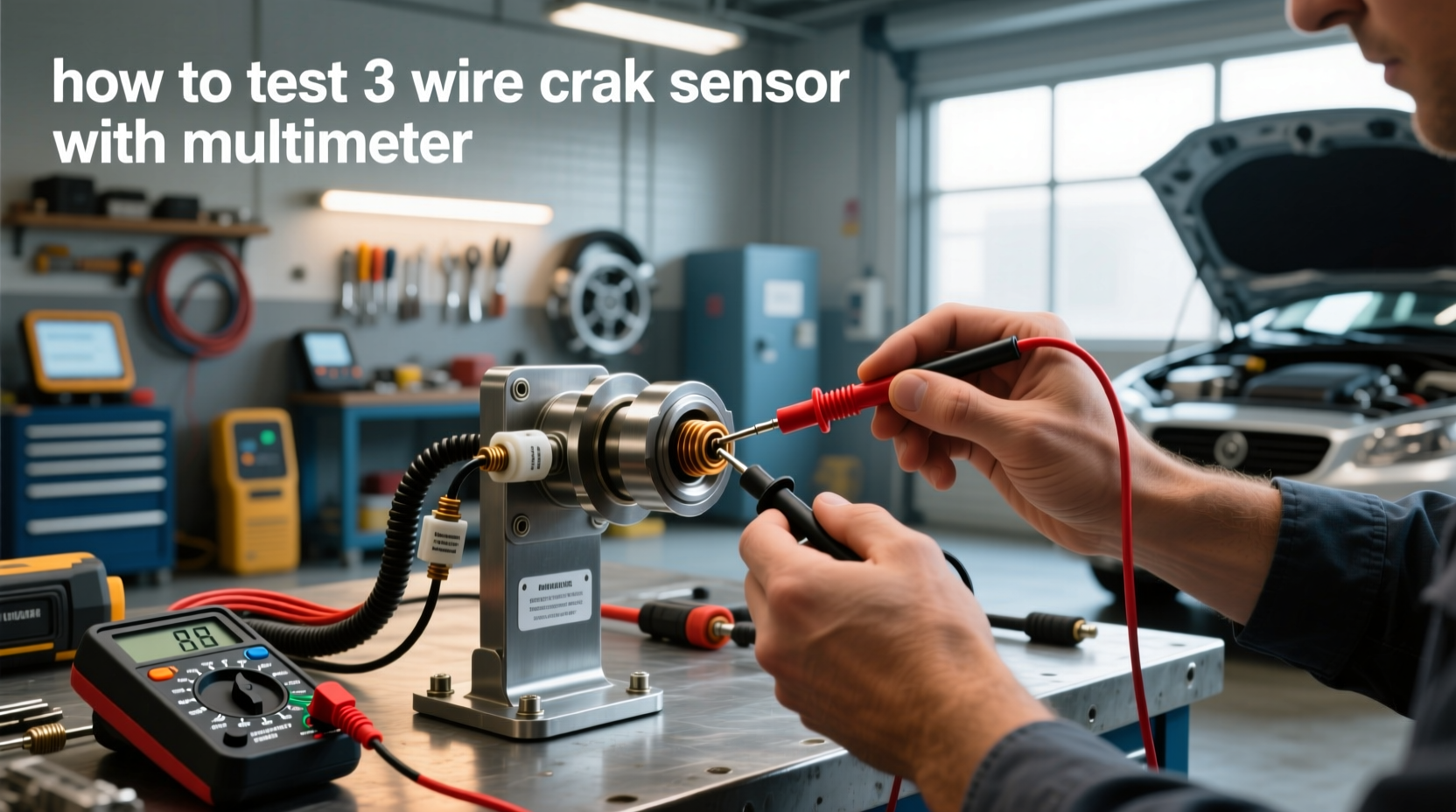
How to Test a 3-Wire Crankshaft Position Sensor
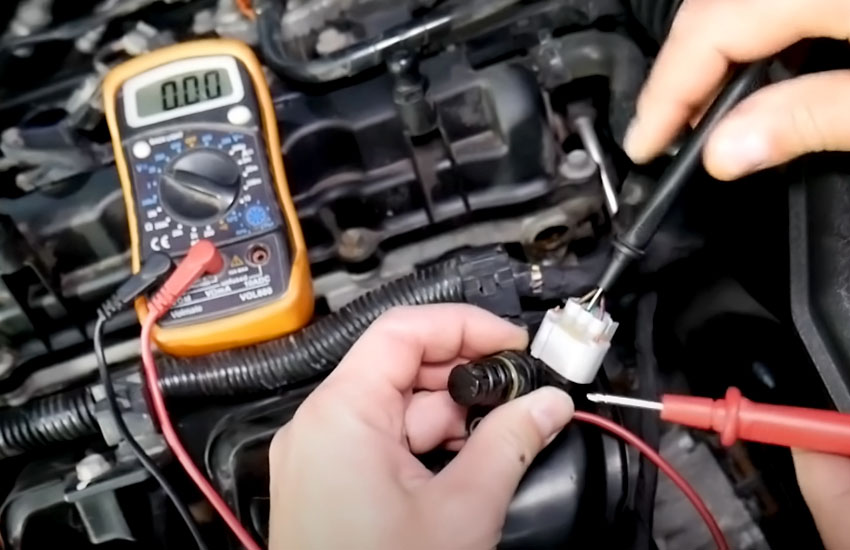
A typical 3-wire Hall-effect crankshaft position sensor requires an external power supply, a ground, and a signal circuit. Because it is a powered electronic sensor, testing it solely with an ohmmeter is generally not the correct diagnostic approach.
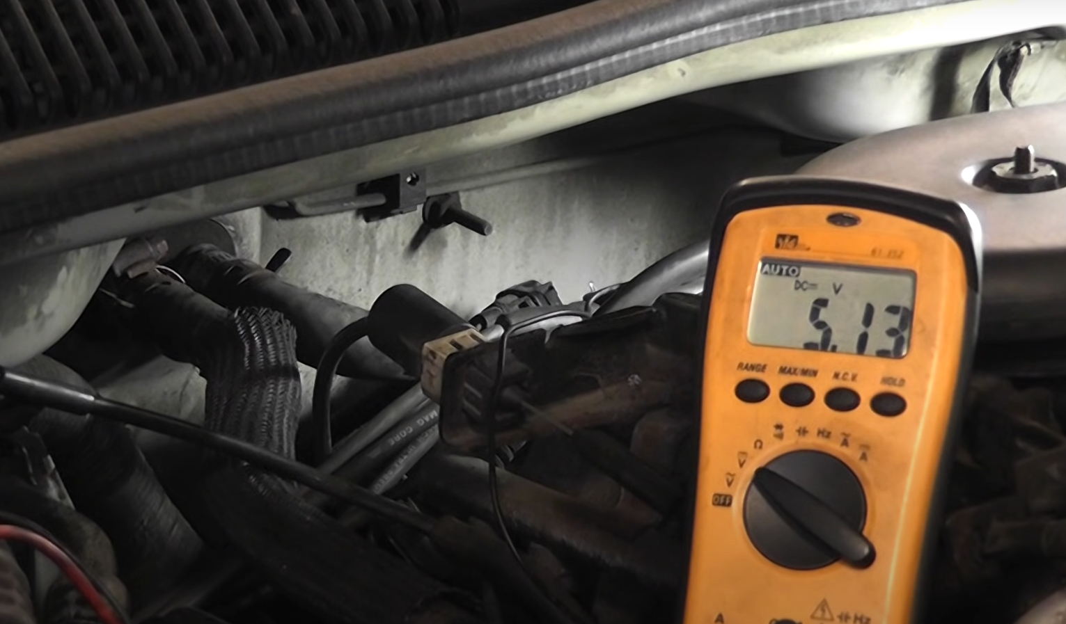
Use the wiring diagram to identify the power, ground, and signal terminals. With the connector attached and the circuit powered as specified, verify the sensor supply voltage first. Depending on the vehicle, the supply may be a regulated reference voltage or another specified system voltage. Never assume that every three-wire sensor uses the same supply.
Next, verify the ground circuit. A voltage measurement can show that ground exists, but a voltage-drop test under operating conditions is often more useful when diagnosing excessive resistance in wiring or connections.
Finally, monitor the signal wire while the engine is being cranked. A Hall-effect sensor normally switches its signal as the trigger pattern passes the sensor. A digital multimeter may display changing or averaged voltage, but an oscilloscope provides a clearer representation of the switching waveform.
Source: harleydavidsonblog.com
Check power
Verify the specified supply voltage at the correct terminal.
Check ground
Confirm that the ground circuit is intact and does not have excessive resistance.
Check signal
Monitor the signal circuit while cranking and look for switching behavior consistent with the manufacturer’s specification.
Do not guess the pinout
Connecting a test lead to the wrong terminal can produce misleading results or potentially damage a circuit.
Power and Ground Are Present but the Signal Does Not Switch
If the correct power and ground reach the sensor but its output does not switch while the crankshaft rotates, the sensor becomes a stronger suspect. Before replacing it, verify that the reluctor or trigger wheel is actually moving past the sensor at the correct distance and that the signal wire is not shorted.
If the signal exists directly at the sensor but does not reach the engine control module, diagnose the harness and connector between those points rather than replacing the sensor.
Crankshaft Position Sensor Test Results Explained
A useful diagnosis considers the complete circuit instead of treating one multimeter reading as proof. The table below summarizes common result patterns and what they suggest.
If the sensor passes basic tests but symptoms remain, waveform testing becomes especially useful. An oscilloscope can reveal intermittent dropouts, inconsistent tooth patterns, electrical noise, or synchronization problems that a digital multimeter may average out.
No cranking RPM and no sensor signal
Investigate the sensor, its power or ground where applicable, the signal wiring, sensor mounting, and trigger wheel.
Sensor signal present but scan tool shows zero RPM
Check the circuit between the sensor and control module and verify the signal at the control-module side using the proper wiring information.
Correct power and ground but no Hall signal
The sensor may be defective, but confirm trigger-wheel movement, air gap, and signal-wire integrity first.
Inductive resistance out of specification
An open, shorted, or out-of-range sensor winding supports replacement when the correct specification and test terminals have been verified.
Normal tests but intermittent stalling remains
Repeat testing when the fault occurs and inspect for heat-related failure, vibration-sensitive wiring, loose terminals, or intermittent signal dropouts.
Why a Trouble Code Does Not Automatically Mean the Sensor Is Bad
A diagnostic trouble code reports what the control module detected, not necessarily which physical part caused it. For example, loss of a crankshaft signal can result from a failed sensor, damaged wiring, connector corrosion, an abnormal sensor gap, a damaged reluctor wheel, or another circuit problem.
Record freeze-frame and related diagnostic information before clearing codes. Replacing a sensor solely because its name appears in a trouble-code description can lead to unnecessary parts replacement.
Common Mistakes When Testing a Crankshaft Position Sensor
Most crankshaft sensor testing errors come from using the wrong procedure or treating generic specifications as universal. Confirming the sensor design and circuit arrangement before connecting the meter prevents many false diagnoses.
Using resistance testing on every sensor
A resistance test is useful for some inductive sensors but is not a universal test for powered Hall-effect sensors.
Assuming two wires or three wires always identify sensor type
Wire count provides a clue but exceptions exist, including shielded circuits.
Replacing the sensor without inspecting wiring
Broken wires, loose pins, corrosion, heat damage, and poor connections can imitate sensor failure.
Ignoring battery and cranking condition
A weak battery or abnormal cranking speed can complicate signal testing and create misleading results.
Using generic resistance specifications
Crankshaft sensor resistance varies by design, so compare measurements with vehicle-specific service information.
Piercing wires unnecessarily
Improper probing can damage insulation and create future corrosion or intermittent electrical faults.
Ignoring the reluctor wheel
Damaged, missing, contaminated, or improperly positioned trigger-wheel features can produce a poor crankshaft signal even when the sensor itself works.
When an Oscilloscope Is Better Than a Multimeter
Use an oscilloscope when basic multimeter tests are inconclusive, particularly with intermittent stalling, synchronization faults, recurring crankshaft codes, or a sensor that appears electrically normal. A scope displays the signal over time rather than reducing it to a single changing voltage value.
A variable-reluctance sensor normally produces an alternating waveform whose frequency increases with crankshaft speed. A Hall-effect sensor typically produces a digital switching waveform. The exact pattern, amplitude, frequency, missing-tooth arrangement, and relationship with the camshaft signal depend on the engine design.
Comparing the measured waveform with verified service information can help distinguish a sensor failure from a damaged reluctor wheel, incorrect air gap, wiring interference, or crank-to-cam timing problem.
Intermittent dropout
A scope can reveal a brief signal loss that a digital meter may not capture.
Damaged reluctor
An irregular pulse pattern can provide evidence of a trigger-wheel problem.
Signal quality
Noise, weak amplitude, distorted switching, and inconsistent spacing are easier to recognize on a waveform.
Crank and cam correlation
A multi-channel scope can compare crankshaft and camshaft signals when synchronization is in question.
What to Do If the Crankshaft Sensor Passes the Test
If the crankshaft position sensor passes its specified tests, do not replace it simply because the symptoms resemble sensor failure. Continue diagnosing the circuit and the other systems required for the engine to run.
For a crank-no-start condition, determine whether the engine has the required ignition, injector control, fuel pressure, mechanical compression, and correct valve timing. The exact diagnostic path depends on the vehicle and engine-management system.
If a crankshaft-related fault keeps returning despite correct sensor operation, inspect the connector and harness under load, verify the sensor mounting and air gap where applicable, inspect the reluctor wheel, and evaluate crankshaft-to-camshaft synchronization. Professional diagnosis with an oscilloscope may be worthwhile when an intermittent fault cannot be reproduced with basic equipment.
Inspect the harness
Check continuity and voltage drop according to the factory diagnostic procedure.
Inspect the trigger wheel
Look for physical damage, incorrect alignment, excessive movement, or other conditions affecting the sensor target.
Check related codes
Camshaft sensor, ignition, timing, voltage, and communication faults may provide additional diagnostic direction.
Test during the failure
Intermittent problems are easiest to identify while the symptom is actually occurring.
Frequently Asked Questions
Q
Can you test a crankshaft position sensor with a multimeter?
Yes. A digital multimeter can test many crankshaft position sensor circuits, but the correct test depends on sensor design. An inductive sensor may be checked for resistance and AC voltage output, while a Hall-effect sensor is normally checked for power, ground, and signal switching. Always use the specifications and pinout for the exact vehicle.
Q
How do you test a crankshaft position sensor without removing it?
Start with an OBD-II scan tool and monitor engine RPM while cranking. You can then inspect the connector and, where the service procedure permits, back-probe a powered sensor to check its supply, ground, and signal with the sensor installed. An oscilloscope is particularly useful because it can evaluate the sensor while it operates in its normal position.
Q
What should a crankshaft position sensor read on a multimeter?
There is no universal multimeter value for every crankshaft position sensor. Resistance, AC output, reference voltage, and signal levels depend on the sensor and vehicle. Use factory or reputable vehicle-specific service information rather than applying a generic resistance or voltage number.
Q
Can a crankshaft position sensor be bad without a trouble code?
Yes. An intermittent sensor or wiring fault may occur too briefly or under conditions that do not immediately set a diagnostic trouble code. Testing while the symptom is present, monitoring live RPM data, and examining the waveform can help locate intermittent faults.
Q
Does zero RPM while cranking mean the crankshaft sensor is bad?
Zero RPM during cranking is an important diagnostic clue, but it does not prove the sensor itself has failed. The problem can also involve sensor power or ground, an open or shorted signal circuit, connector damage, an incorrect sensor gap, the trigger wheel, or the control module’s ability to receive the signal.
Q
Can you test a 3-wire crankshaft sensor with an ohmmeter?
A resistance test is generally not the primary way to diagnose a powered Hall-effect crankshaft sensor. These sensors normally need power and ground to produce their output, so testing focuses on supply voltage, ground quality, and signal switching according to the wiring diagram.
Q
Should I replace the crankshaft sensor if I have code P0335?
Not automatically. P0335 indicates a problem involving the crankshaft position sensor A circuit or its expected signal, but the root cause can be the sensor, wiring, connector, reluctor wheel, installation, or another circuit issue. Test the circuit before replacing parts.
✦ Wrapping Up
Conclusion
Knowing how to test crankshaft position sensor operation can prevent unnecessary parts replacement and make a no-start or stalling diagnosis much more systematic. Begin with the battery, trouble codes, live cranking RPM, connector, and wiring. Then identify the sensor type before choosing an electrical test.
For a 2-wire inductive sensor, resistance and generated AC voltage are commonly useful checks. For a 3-wire Hall-effect sensor, verify the specified power supply, ground, and switching output. In every case, compare measurements with specifications for your exact vehicle rather than relying on a universal resistance or voltage value.
If the electrical tests look normal but the problem remains, investigate the harness, connector terminals, sensor mounting, air gap, reluctor wheel, and related engine-management systems. An oscilloscope or qualified automotive technician can provide the next level of diagnosis when an intermittent or waveform-related fault cannot be confirmed with basic tools.
💡 Key Takeaway
Start by connecting an OBD-II scanner and checking for a believable RPM signal while cranking. If the signal is missing, identify the sensor type and use your vehicle’s wiring diagram and specifications to test the sensor, power, ground, signal circuit, and wiring before replacing any parts.
Ethan Brooks is an automotive writer at Auto News 7, covering car news, vehicle maintenance, new model updates, recalls, and practical buying guides. He focuses on clear, useful information that helps drivers understand their vehicles and make better ownership decisions.