To test crankshaft position sensor wiring, identify the correct CKP circuit from vehicle-specific service information, inspect the connector and harness, verify power and ground where applicable, check the signal while cranking, and test each wire for continuity, opens, shorts to ground, and shorts to voltage.
For drivers and DIY mechanics working on vehicles in the United States, crankshaft position sensor circuit problems commonly show up as a Check Engine Light, an intermittent stall, extended cranking, a crank-no-start condition, or diagnostic trouble codes such as P0335 through P0339. On modern U.S.-market vehicles, however, a crankshaft position sensor code does not automatically prove that the sensor itself is defective. The connector, wiring harness, power supply, sensor ground, reluctor wheel, or engine control module circuit can also be involved.
The most reliable approach is to diagnose the circuit rather than replace parts based only on a trouble code. You will usually need a digital multimeter, the correct wiring diagram or service information for your year, make, model, and engine, and preferably a scan tool. An oscilloscope provides a much clearer picture of the actual crankshaft signal when a difficult intermittent problem is involved. Because CKP designs vary substantially between vehicles, do not assume wire functions or expected voltages from wire color alone.
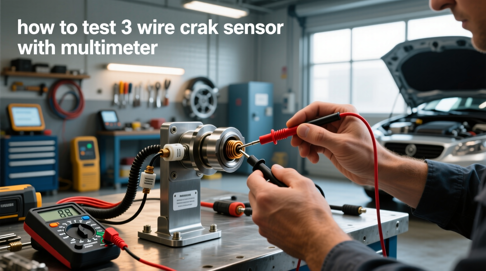
Source: youtube.com
What You Need Before Testing Crankshaft Position Sensor Wiring
Start with the wiring diagram for the exact vehicle. This is more important than owning an expensive meter because you must know which terminal is power, ground, signal, shielding, or a second signal circuit before touching the connector. A diagram also tells you where the CKP wires terminate at the engine control module, often called the ECM or PCM.
A digital multimeter is sufficient for basic power, ground, continuity, and short-circuit checks. A scan tool is helpful because engine RPM during cranking gives you a quick indication of whether the control module is detecting crankshaft movement. An oscilloscope is preferred when you need to evaluate signal shape, amplitude, missing pulses, electrical interference, or an intermittent dropout.
Before electrical testing, perform a careful visual inspection. Follow the harness from the CKP sensor as far as practical. Look for wires touching an exhaust component, oil-soaked insulation, stretched wiring near an engine mount, broken conduit, corrosion inside the connector, pushed-back terminals, loose pins, water intrusion, or previous repairs.
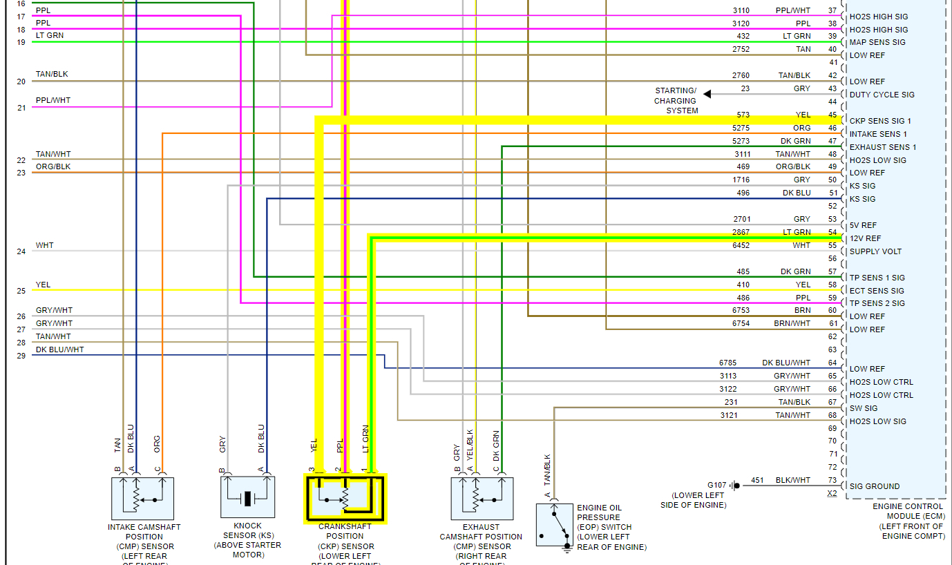
Source: storage.googleapis.com
Digital multimeter
Use it for DC voltage, AC voltage when appropriate, resistance, continuity, and short-circuit testing.
Vehicle wiring diagram
Confirm CKP connector pin numbers and the function of every terminal instead of relying on generic wire colors.
Scan tool
Monitor engine RPM while cranking and check for CKP-related diagnostic trouble codes.
Back-probe pins
Use suitable probes that let you measure a live circuit without spreading or damaging connector terminals.
Oscilloscope when available
Use it to evaluate the waveform when a multimeter cannot reveal intermittent or high-speed signal problems.
Follow Basic Electrical Safety
Keep hands, test leads, clothing, and tools away from belts, pulleys, fans, and other moving components whenever the engine is being cranked or run. Support the vehicle correctly if access requires working underneath it. Do not crawl under a vehicle supported only by a jack.
Avoid forcing probes into connector terminals. A spread terminal can create a new intermittent fault. Whenever resistance or continuity is being measured, de-energize the circuit and disconnect the components specified by the service procedure.
Do not short terminals
Accidentally connecting a reference-voltage terminal directly to ground can damage wiring or an electronic control circuit.
Do not guess pin functions
Confirm the circuit from reliable vehicle-specific service information before applying a meter.
Identify the Crankshaft Position Sensor Type Before Testing
The testing procedure depends heavily on the sensor design. Two widely used CKP designs are variable-reluctance inductive sensors and Hall-effect sensors. An inductive sensor generates a voltage as the reluctor teeth pass the sensor. A Hall-effect sensor normally requires an external electrical supply and produces a switching signal that the control module interprets.
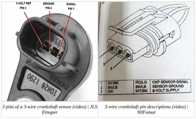
A two-terminal sensor is often an inductive design, while a three-terminal sensor is frequently a Hall-effect design. These are useful clues, not universal rules. Some sensors use shielding, additional circuits, or connector arrangements that make identification by pin count unreliable. Confirm the design before measuring resistance or applying any test procedure.
This distinction matters because resistance testing that may be acceptable for an inductive sensor should not automatically be performed across an unknown Hall-effect sensor. Some electronic sensors can be damaged by inappropriate resistance testing. When the sensor type is unknown, identify it from the service manual before proceeding.
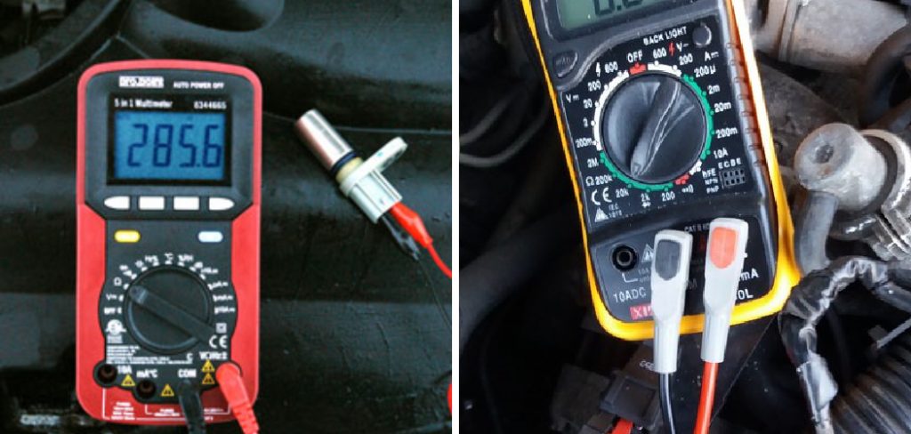
Source: carinterior.alibaba.com
Inductive CKP sensor
Usually generates an alternating voltage whose amplitude generally rises as crankshaft speed increases.
Hall-effect CKP sensor
Normally uses a supply circuit and ground and produces a digital switching signal.
Do not identify by color
Wire colors differ among manufacturers, engines, model years, and harness revisions.
Check Scan Tool RPM Before Opening the Harness
If you have a scan tool, watch the engine-speed parameter while a helper cranks the engine. An RPM reading indicates that the control module is detecting crankshaft movement, although it does not prove that every part of the CKP circuit is perfect. No RPM reading makes the sensor, its wiring, its power or ground circuits, the reluctor, or the receiving control-module circuit more relevant diagnostic targets.
Do not replace the CKP sensor based on the RPM reading alone. Treat the scan result as one piece of evidence and continue with circuit testing.
RPM displayed
The control module is receiving enough crankshaft information to calculate engine speed at that moment.
No RPM displayed
Continue with connector, circuit, sensor, and reluctor checks rather than assuming the sensor alone has failed.
How to Test Crankshaft Position Sensor Wiring Step by Step
Testing crankshaft position sensor wiring is easiest when you separate the job into power, ground, signal, continuity, and short-circuit checks. Do not begin by randomly probing every terminal. Identify the circuit first and work through the checks in a controlled sequence.
If the vehicle uses a three-wire powered sensor, you will commonly be checking a supply circuit, a ground circuit, and a signal circuit. A reference or supply near 5 volts is common on many systems, but other arrangements exist, so the manufacturer’s specification is the deciding value. If the vehicle uses a passive two-wire inductive sensor, the test focuses more on the sensor-generated signal and the integrity of both signal wires.
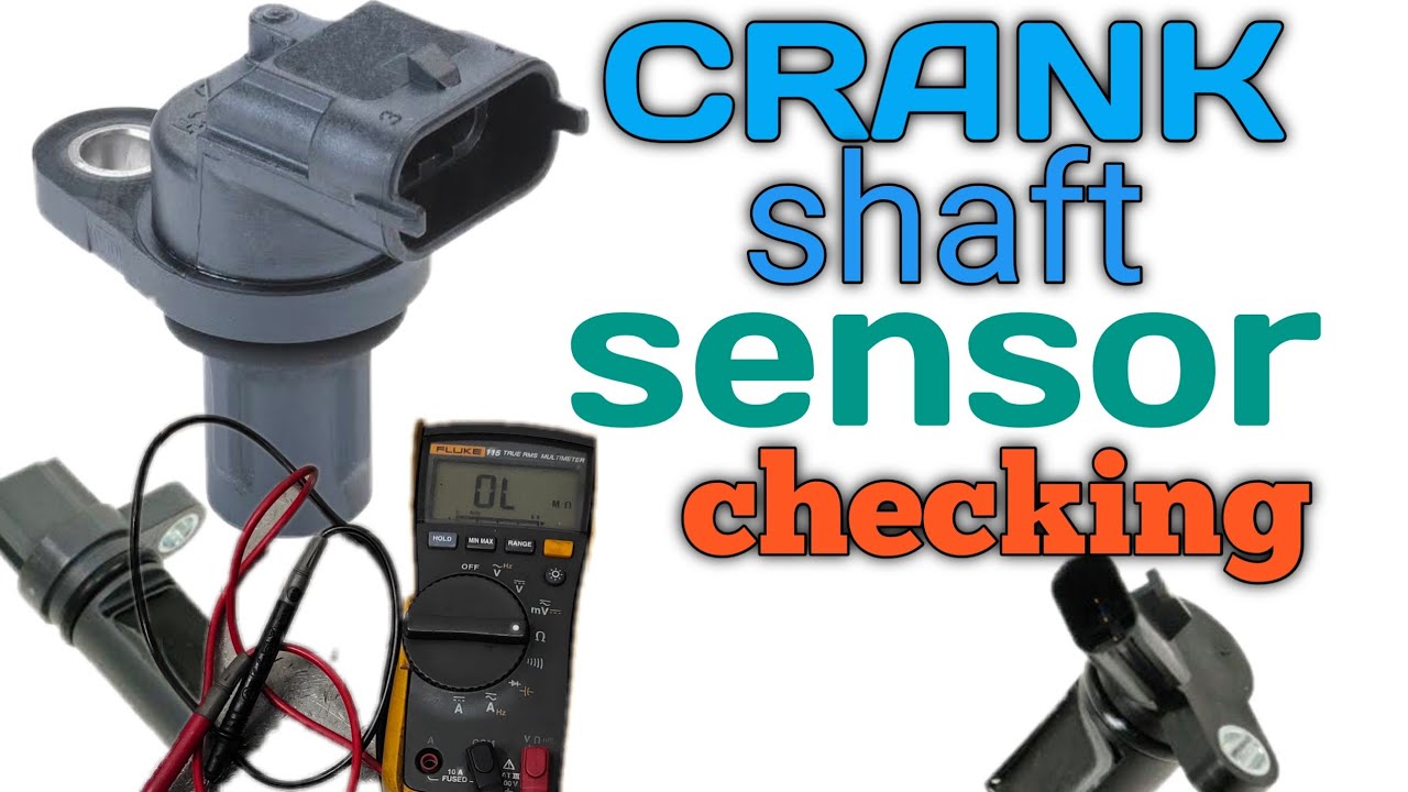
Source: nissankaengine.com
Step 1: Inspect the connector
Disconnect the CKP connector and check for bent, loose, corroded, contaminated, recessed, or damaged terminals. Inspect the connector lock and harness strain relief.
Step 2: Identify every circuit
Use the wiring diagram to label the power or reference circuit, sensor ground, signal wire, and any shielding or additional circuit.
Step 3: Verify the supply voltage
For a powered sensor, switch the ignition on as directed by service information and measure between the appropriate supply and ground terminals. Compare the reading with the manufacturer’s specification.
Step 4: Verify the ground
Test the sensor ground according to the service procedure. A voltage-drop test under operating conditions is often more informative than a simple continuity beep because a damaged connection may show continuity yet fail under load.
Step 5: Check the CKP signal
Reconnect the sensor and back-probe the signal circuit if the procedure permits. Crank the engine and watch for the specified signal. An oscilloscope is the preferred tool for confirming waveform quality.
Step 6: Test wire continuity
With power removed and the relevant sensor and control-module connectors disconnected, measure the CKP circuit from one end of the harness to the other. Compare resistance with the vehicle manufacturer’s limit.
Step 7: Check for shorts
With the circuit safely isolated, test whether a signal wire is shorted to ground, battery voltage, a reference-voltage circuit, or another wire in the harness.
Step 8: Perform a wiggle test
While monitoring continuity, voltage, scan data, or a waveform as appropriate, gently move suspect portions of the harness and connector to expose an intermittent open or poor terminal connection.
How to Test CKP Power
Set the multimeter to DC volts. With the connector and ignition state configured as the service information specifies, place the meter leads across the correct supply and ground points. A missing supply does not prove that the CKP sensor is defective. Trace the supply circuit toward its source and determine whether the problem is an open wire, shorted shared reference circuit, connector issue, fuse or relay issue where applicable, or control-module problem.
If several sensors share the same reference-voltage circuit, one shorted sensor or damaged branch of the harness can pull the shared voltage low. Multiple seemingly unrelated sensor codes can therefore be a useful clue.
Correct supply present
Continue with ground and signal testing.
Supply missing or low
Diagnose the supply circuit before condemning the CKP sensor.
How to Test CKP Ground
A poor ground can make a good sensor appear defective. Check the ground circuit using the manufacturer’s preferred method. When possible, testing voltage drop while the circuit is operating helps reveal resistance that a basic continuity test can miss.
If the ground is poor, inspect splices, shared sensor grounds, connector terminals, damaged wiring, and the control-module ground path described in the wiring diagram.
Stable ground
Proceed to the signal circuit.
Excessive voltage drop
Repair the high-resistance ground path and retest the system.
How to Test the Signal Wire
For a Hall-effect CKP sensor, an oscilloscope should normally show a switching waveform as the crankshaft rotates. The exact high and low levels, frequency, pattern, and missing-tooth characteristics depend on the vehicle. A multimeter may show an averaged or changing voltage, but it can miss fast glitches that a scope reveals.
For a variable-reluctance sensor, set the meter or scope for the test specified by the manufacturer. These sensors normally produce an alternating signal whose amplitude depends on factors including cranking speed, sensor design, air gap, and reluctor condition. Do not apply a universal minimum voltage to every vehicle.
Good waveform at sensor
If the control module does not receive the same information, investigate the harness and connector between the sensor and module.
No sensor output
Verify sensor supply and ground where applicable, sensor condition, air gap, installation, and reluctor operation.
How to Find an Open, Short, or High-Resistance CKP Wire
A crankshaft position sensor harness can fail even when the insulation looks normal. Copper strands can break inside the insulation, connector crimps can loosen, and wires can rub through against brackets or engine components. This is why continuity, short-circuit, and wiggle testing are valuable after the basic power, ground, and signal checks.
Before measuring resistance, turn the ignition off and isolate the circuit as instructed by the service information. Disconnecting both ends of the wire prevents the meter from measuring through electronic components or parallel circuits. Measure from the CKP connector terminal to the corresponding control-module terminal and compare the result with the manufacturer’s specification.
A very low-resistance path from end to end generally indicates continuity, but continuity alone does not guarantee that a circuit can perform correctly under operating conditions. A partially broken conductor or poor terminal may behave differently when hot, vibrating, or carrying current. This is one reason voltage-drop and waveform testing can be more revealing.
Source: safetyfic.com
Open circuit
The meter indicates no usable electrical path through a wire that should be continuous. Look for breaks, loose terminals, damaged splices, or disconnected connectors.
Short to ground
An isolated circuit unexpectedly has continuity to chassis or ground. Inspect for rubbed-through insulation or contamination inside connectors.
Short to voltage
A circuit that should not carry supply voltage shows voltage because it contacts a powered circuit or has an internal electrical fault elsewhere.
Short between circuits
Two isolated wires show unintended continuity to each other, often because insulation has melted, rubbed through, or been damaged in a previous repair.
Intermittent connection
Readings change when the connector or harness is moved, suggesting a broken conductor, terminal-tension problem, or poor splice.
Use Connector-to-Connector Testing to Separate Sensor and Wiring Faults
A useful diagnostic strategy is to compare the signal near the sensor with the signal near the control module. If a clean waveform exists at the CKP sensor but becomes distorted or disappears before reaching the module, the harness or connector path deserves attention. If the same proper waveform reaches the control module and the module still reports no crankshaft signal, diagnosis moves toward pin fit, control-module inputs, timing relationships, and vehicle-specific procedures.
Do not condemn an engine control module until the sensor circuit, related grounds and supplies, connector condition, reluctor, and applicable mechanical conditions have been verified. Control modules can fail, but wiring and connector faults should be ruled out first.
Signal at sensor but not module
Concentrate on the wiring and connectors between those measurement points.
Signal present at both ends
Follow the manufacturer’s diagnostic tree before considering a control-module fault.
How to Interpret Your Test Results and Avoid Common Mistakes
The goal of CKP wiring diagnosis is to determine where the expected electrical behavior stops. If the sensor lacks its required supply, repairing or replacing the sensor will not restore that missing supply. If power and ground are good but the sensor produces no valid output while the crankshaft is turning, the sensor, its installation, the reluctor, or the mechanical relationship between them becomes more suspicious. If the sensor output is correct at the sensor but not at the PCM, the harness path becomes the primary focus.
One of the most common mistakes is replacing the crankshaft position sensor immediately after reading a P0335 code. P0335 describes a crankshaft position sensor circuit malfunction. The circuit includes more than the sensor itself. Opens, shorts, damaged connectors, a reluctor problem, and other electrical or mechanical faults can produce similar symptoms.
Another mistake is treating generic voltage or resistance numbers as universal specifications. Sensor technology differs between manufacturers and even between engines from the same manufacturer. The correct test value is the specification for the exact vehicle and engine being diagnosed.
Source: harleydavidsonblog.com
Power missing
Trace the supply circuit and check whether other sensors sharing that supply are also affected.
Ground defective
Repair the ground circuit, connector, splice, or related wiring and repeat the test.
Power and ground good but no Hall signal
Verify the specified sensor test, installation, reluctor condition, air gap where applicable, and signal circuit before replacing parts.
Inductive signal absent
Check the sensor, wiring, sensor gap where specified, cranking speed, connector condition, and reluctor movement.
Signal good at CKP but missing at PCM
Look for an open, short, poor splice, terminal problem, or damaged harness between the two points.
Fault occurs only hot or while driving
Use a wiggle test, temperature-dependent testing, scan-data recording, or oscilloscope capture to investigate an intermittent fault.
Common Diagnostic Mistakes
Avoid probing wires without a diagram, piercing insulation unnecessarily, measuring resistance on a powered circuit, and assuming every three-wire sensor uses the same pin arrangement. Also avoid using a continuity buzzer as the only test of a critical wire. The buzzer can confirm that some electrical connection exists, but it does not show waveform quality or necessarily expose a high-resistance connection under real operating conditions.
Do not overlook mechanical causes. A damaged reluctor wheel, incorrect sensor installation, excessive air gap on designs where gap is critical, debris at the sensor, or a timing-related mechanical fault can disrupt the CKP signal even when the external wiring tests correctly.
Wrong pin identification
Can produce misleading readings or an accidental short.
Testing only the sensor
May miss an open circuit or poor connector between the CKP sensor and PCM.
Ignoring mechanical input
A perfect electrical circuit cannot create a correct signal if the sensor cannot properly detect the reluctor.
When to Get Professional Diagnostic Help
Professional diagnosis is sensible when the wiring diagram is unavailable, the circuit disappears into a complex shared harness, the fault is intermittent, a scope is required to evaluate waveform synchronization, or testing points are difficult to access safely. It is also appropriate when service information requires measurements directly at an expensive control module and you are not comfortable back-probing electronic circuits.
A technician with an oscilloscope can compare CKP and camshaft signals, identify missing or distorted pulses, and determine whether an apparent electrical fault is actually caused by timing or reluctor problems.
Seek help for uncertain pinouts
Guessing at control-module terminals risks creating additional electrical problems.
Seek help for intermittent waveform faults
A scope and recording equipment can capture a signal dropout that occurs too quickly for a multimeter to show.
Frequently Asked Questions About How to Test Crankshaft Position Sensor Wiring
Q
How many wires does a crankshaft position sensor have?
Many inductive crankshaft position sensors use two primary signal wires, while many Hall-effect sensors use three circuits for power, ground, and signal. That pattern is not universal. Shielding and other design variations can change the connector arrangement, so confirm the sensor type and pinout from service information.
Q
Should a crankshaft position sensor have 5 volts?
Some powered CKP sensors use a reference or supply near 5 volts, but 5 volts is not a universal specification for every crankshaft position sensor. Passive inductive sensors generate their own signal and operate differently. Check the wiring diagram and voltage specification for the exact vehicle before interpreting the reading.
Q
Can bad crankshaft position sensor wiring cause a P0335 code?
Yes. P0335 refers to a crankshaft position sensor A circuit malfunction, and damaged wiring, an open signal circuit, a short to ground, a short to voltage, connector problems, or a failed sensor can all be relevant. Mechanical problems affecting the reluctor or crankshaft signal can also contribute, depending on the vehicle.
Q
Can I test crankshaft position sensor wiring with only a multimeter?
A multimeter can perform many useful checks, including supply voltage, ground, continuity, resistance where appropriate, shorts, and a basic signal test. It cannot display the detailed waveform as clearly as an oscilloscope. Intermittent dropouts, distorted pulses, electrical noise, and synchronization problems are often much easier to diagnose with a scope.
Q
Why do I still have a crankshaft sensor code after replacing the sensor?
The replacement sensor may not have addressed the actual fault. Check the connector, power and ground circuits, signal wiring, shared reference-voltage circuits, harness continuity, terminal fit, sensor installation, reluctor condition, and vehicle-specific diagnostic requirements. A new sensor does not repair damaged wiring.
✦ Wrapping Up
Conclusion
Learning how to test crankshaft position sensor wiring is mainly about isolating the circuit one section at a time. Begin with the correct vehicle wiring diagram, inspect the connector and harness, identify the CKP sensor type, and then verify the required power, ground, and signal. If those checks expose no obvious problem, test the harness for continuity, shorts, poor terminal contact, and intermittent faults.
Do not rely on a generic resistance number, wire color, or trouble code to decide that a sensor is bad. Compare every important measurement with the service specifications for the exact year, make, model, engine, and sensor design. When the basic electrical tests are correct but the fault remains, an oscilloscope and a professional diagnostic procedure can help separate wiring faults from sensor, reluctor, timing, and control-module problems.
💡 Key Takeaway
Start by finding the exact CKP wiring diagram for your vehicle. Verify the sensor type and pin functions, then test supply, ground, signal, continuity, and shorts in that order before replacing the crankshaft position sensor or control module.
Ethan Brooks is an automotive writer at Auto News 7, covering car news, vehicle maintenance, new model updates, recalls, and practical buying guides. He focuses on clear, useful information that helps drivers understand their vehicles and make better ownership decisions.
Learn how to remove a camshaft position sensor safely with this detailed step-by-step guide. Discover required tools, common mistakes, troubleshooting tips, and what to do after removal.
Learn how to check camshaft position sensor operation, wiring, voltage, and signal output. Follow this practical step-by-step guide to diagnose common camshaft sensor problems.