To test a 3 wire crankshaft position sensor, identify its power, ground, and signal circuits, verify the correct supply voltage and ground first, then back-probe the signal wire while cranking the engine. A working active sensor should produce a changing signal as the crankshaft rotates.
For drivers and DIY mechanics working on cars and light trucks in the United States, crankshaft position sensor problems commonly enter the diagnostic process after a no-start, intermittent stall, extended cranking, misfire-like complaint, or an OBD-II crankshaft-position circuit code such as P0335. Replacing the sensor immediately can be expensive and may not fix the vehicle because damaged wiring, a poor connector, loss of reference voltage, a bad ground, or a damaged trigger wheel can create similar symptoms.
Learning how to test 3 wire crankshaft position sensor circuits properly starts with an important distinction: three wires usually indicate an active sensor that needs electrical power, but wire count alone does not prove that every sensor works exactly the same way. Many use Hall-effect technology, while some vehicles use other active sensor designs. Supply voltage, pin arrangement, signal behavior, and test specifications vary by manufacturer and model. The safest approach is therefore to identify the three circuits from the vehicle wiring diagram and compare your measurements with factory specifications rather than relying on wire color or a universal voltage number.
A digital multimeter can perform useful power, ground, and basic signal checks without removing the sensor. For the most accurate assessment of the crankshaft signal, however, an oscilloscope is superior because it displays individual pulses that a conventional multimeter may average together. This guide explains both the practical multimeter procedure and the point at which a scan tool or scope becomes the better diagnostic choice.
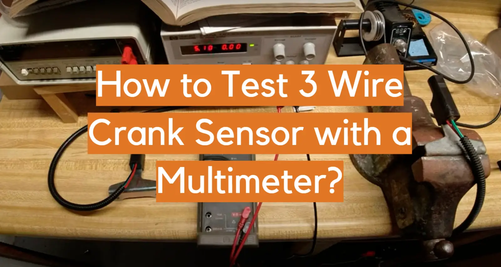
Source: youtube.com
What a 3 Wire Crankshaft Position Sensor Does
The crankshaft position sensor, commonly abbreviated CKP sensor, tells the powertrain control module where the crankshaft is in its rotation and how fast it is turning. The control module uses this information as part of its strategy for ignition timing, fuel injection, misfire monitoring, and other engine-management functions.
A typical active three-wire CKP circuit contains a power supply, a ground or low-reference circuit, and a signal circuit. As the crankshaft’s trigger wheel passes the sensing element, the sensor changes its output in a pattern the control module can interpret as crankshaft position and speed.
Many three-wire CKP sensors are Hall-effect devices that generate a digital switching signal. That does not mean every three-wire sensor can be tested with one universal voltage specification. Some manufacturers use a 5-volt reference, some applications may use a higher supply, and certain active sensors have different signal strategies. Always treat the vehicle’s wiring diagram and service specifications as the deciding reference.
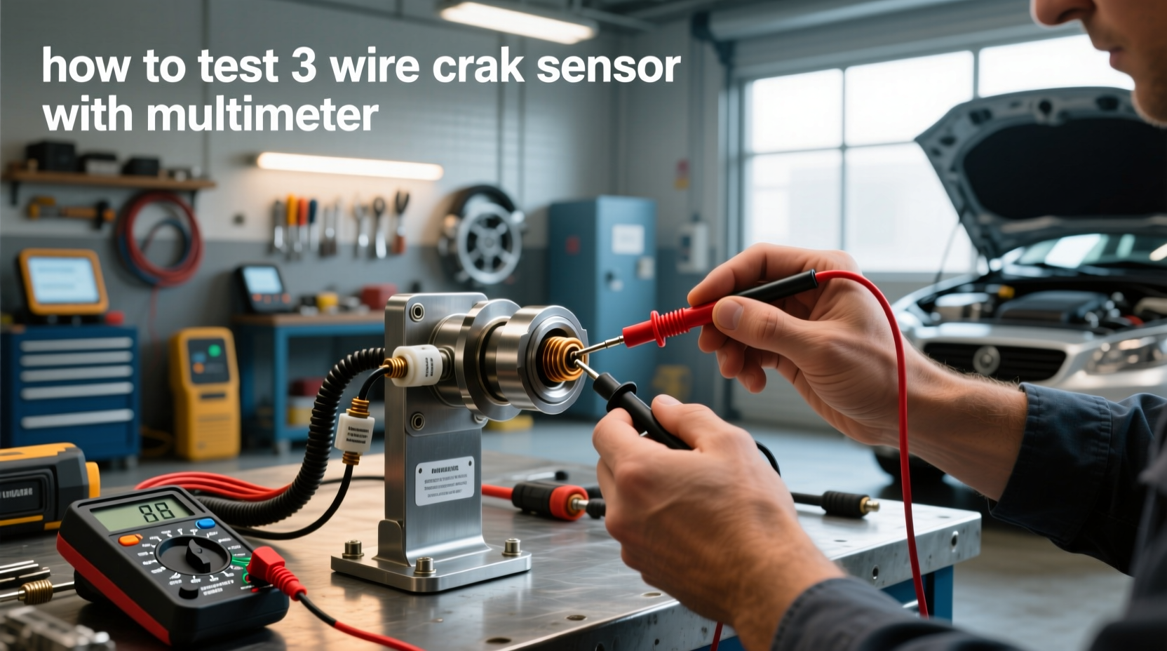
Source: easycarelectrics.com
Power circuit
Provides operating voltage to the active sensor.
Ground circuit
Provides the electrical return path or low reference required for sensor operation.
Signal circuit
Carries crankshaft-position information from the sensor to the engine or powertrain control module.
Why Three Wires Matter During Diagnosis
A two-wire passive magnetic sensor can generate its own alternating voltage as a toothed wheel moves past it. An active three-wire sensor normally requires external power and ground. Consequently, checking only the sensor output can lead to a false diagnosis. If reference voltage or ground is missing, a perfectly functional sensor may produce no usable output.
Tools and Information You Need Before Testing
The most important item is not the multimeter. It is reliable service information for the exact year, make, model, engine, and preferably the vehicle identification details needed to select the correct engine configuration. You need to know which connector terminal is power, which is ground, which is signal, and what voltage or waveform the manufacturer expects.
Use thin automotive back-probes whenever possible. Forcing oversized meter probes into a connector can spread the terminals and create a new intermittent fault. Piercing wire insulation is also best avoided because moisture can later enter the conductor unless the puncture is properly sealed.
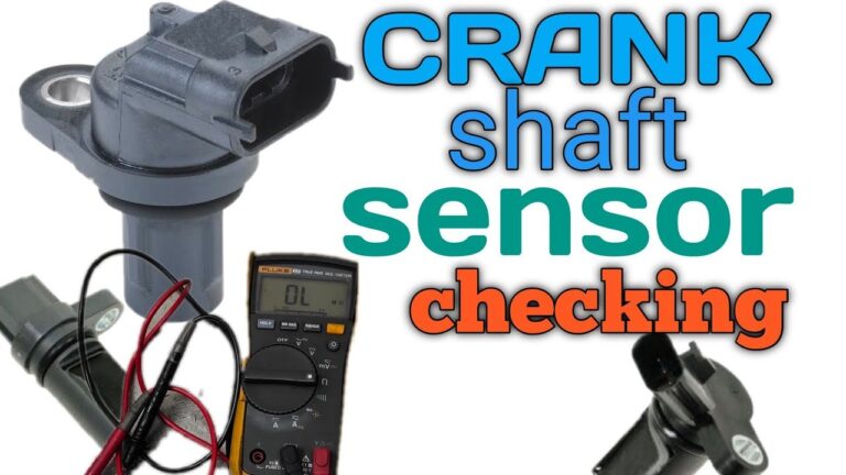
Source: electronicshacks.com
Digital multimeter
Use a meter capable of measuring DC voltage accurately. Frequency or duty-cycle capability can be useful if the manufacturer specifies those tests.
Back-probe leads
Thin probes let you measure a connected circuit without damaging connector terminals.
Vehicle wiring diagram
Use it to identify the CKP power, ground, and signal terminals instead of guessing from wire colors.
Scan tool
Optional but useful for observing engine RPM during cranking and checking diagnostic trouble codes.
Oscilloscope
Optional but preferred when the multimeter cannot clearly establish whether the signal pulses are correct.
Safety Before Cranking the Engine
Park on a level surface, select Park or Neutral as appropriate, set the parking brake, and keep hands, clothing, leads, and tools away from belts, pulleys, fans, and other moving components. Secure meter leads so they cannot be pulled into the accessory drive.
If the test requires extended cranking without allowing the engine to start, use the manufacturer-approved method for disabling fuel or ignition. Do not improvise by disconnecting components if doing so could damage the ignition system, catalytic converter, or control electronics.
How to Test 3 Wire Crankshaft Position Sensor Step by Step
The most reliable multimeter sequence is to inspect the circuit, identify the pins, verify power, verify ground, and only then evaluate the signal. This order prevents a missing supply or bad ground from being mistaken for a failed CKP sensor.
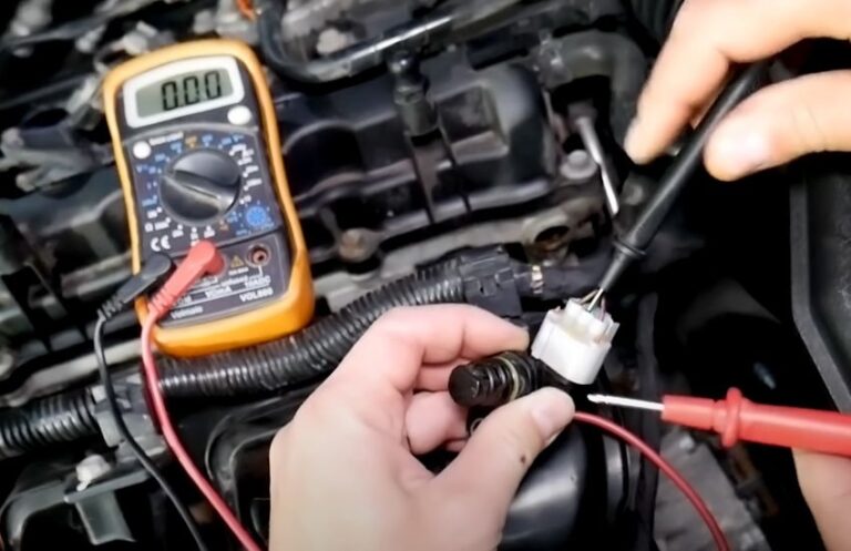
Source: toolsgalorehq.com
Step 1: Inspect the Sensor, Connector, and Harness
Begin with the ignition off. Locate the CKP sensor using the vehicle service information. Depending on the engine, it may be near the crankshaft pulley, timing cover, engine block, flywheel, flexplate, or transmission bellhousing.
Inspect the connector for broken locks, bent or pushed-back terminals, water intrusion, engine oil contamination, corrosion, and loose terminal tension. Follow as much of the harness as practical and look for abrasion, heat damage, previous repairs, pinched wires, or insulation melted against an exhaust component.
Also inspect the sensor body and mounting area. A loose sensor, damaged mounting surface, metal debris, incorrect installation, or excessive sensor-to-trigger-wheel gap can affect the signal even when the electrical circuits appear normal.
Connector damage
Look for corrosion, damaged seals, bent terminals, poor retention, or pins pushed backward into the connector.
Harness damage
Check areas close to the engine, brackets, exhaust, and moving components for rubbing or heat damage.
Sensor mounting
Confirm that the sensor is secure and positioned as specified for the vehicle.
Step 2: Identify Power, Ground, and Signal Pins
Do not assume that red means power, black means ground, or the center terminal is the signal. Automotive manufacturers use different wire colors and connector layouts between models and even between engine options within the same model.
Use the wiring diagram to record the terminal identification before touching the connector with a meter. Note whether the diagram shows a 5-volt reference, battery-voltage supply, sensor low reference, chassis ground, pull-up circuit, or any special test conditions.
Step 3: Check the Sensor Power Supply
Set the digital multimeter to DC volts. Follow the manufacturer procedure for whether the sensor should remain connected or be disconnected during the supply test. With the ignition in the specified position, measure between the sensor power circuit and its specified ground or low-reference circuit.
Many automotive active sensors operate from approximately 5 volts, while other applications can use a different supply. Do not condemn the circuit merely because it does not match a generic internet value. Compare the measurement with the specification for that exact vehicle.
If the expected voltage is missing, stop before replacing the sensor. Investigate the supply circuit for an open wire, short to ground, connector problem, shared-reference fault, fuse issue where applicable, or control-module problem.
Step 4: Verify the Ground Circuit
A simple continuity beep is not always enough to prove that a circuit can carry current correctly. A corroded or partially broken connection can show continuity while developing excessive voltage drop under load.
When the service procedure allows it, evaluate the sensor ground with the circuit operating and measure voltage drop between the sensor ground and the appropriate battery or chassis reference. The acceptable limit varies by vehicle, so use the manufacturer’s specification rather than an arbitrary universal cutoff.
If the ground is poor, repair that circuit before evaluating the CKP signal. A bad ground can make the signal remain fixed, become noisy, or disappear completely.
Step 5: Back-Probe the Signal Wire
Reconnect the sensor if it was disconnected. Keep the connector plugged in because the operating signal normally needs to be observed with the sensor powered and the circuit connected to the control module.
Set the multimeter to DC volts unless the manufacturer’s test procedure specifies frequency, duty cycle, or another setting. Connect the negative meter lead to the specified low reference or reliable ground and carefully back-probe the signal terminal with the positive lead.
Have an assistant crank the engine while you watch the display. A conventional meter may show a changing value or an averaged voltage rather than visibly alternating between the signal’s true high and low levels. That limitation is normal because the crankshaft produces pulses faster than many handheld meter displays can refresh.
If the signal remains completely fixed, do not automatically replace the sensor. First confirm correct power and ground, inspect the signal wire for an open or short, verify the sensor air gap and trigger wheel when accessible, and consider testing the waveform with an oscilloscope.
How to Interpret Your Multimeter Results
The value of the test comes from combining the three circuit checks rather than looking at one voltage in isolation. A missing CKP signal has a different meaning when sensor power is absent than it does when both power and ground are confirmed good.
Use the following diagnostic logic as a general framework, then compare actual voltages with factory specifications.
Source: carinterior.alibaba.com
Power missing
Investigate the power or reference circuit before blaming the crankshaft sensor.
Ground faulty
Repair the ground or low-reference problem and repeat the signal test.
Power and ground good but no signal
The sensor becomes a stronger suspect, but wiring between the sensor and control module, sensor installation, air gap, and trigger-wheel condition must still be considered.
Signal changes during cranking
The sensor is producing an output, but a multimeter alone may not prove that the waveform has correct amplitude, timing, pulse width, or tooth pattern.
Signal appears normal but the engine still will not start
Continue diagnosis instead of replacing the sensor. Check scan data, related codes, camshaft synchronization where applicable, ignition, fuel delivery, mechanical timing, and other causes appropriate to the vehicle.
Example Diagnostic Decision Table
Suppose the wiring diagram calls for a 5-volt sensor supply. If the power terminal has no voltage, the missing signal is expected and does not establish that the CKP sensor is bad. If supply voltage and ground are correct but the signal does not react at all while the crankshaft rotates, the sensor, signal circuit, trigger wheel, or mechanical relationship between them deserves closer investigation.
If a scope shows a clean, repeatable crankshaft waveform reaching the control module but scan data still shows no engine speed, diagnosis may need to move toward connector integrity, module inputs, synchronization logic, or vehicle-specific control-system faults.
Why You Should Not Rely on a Resistance Test
One of the most common mistakes when learning how to test 3 wire crankshaft position sensor circuits is treating an active sensor like a passive two-wire magnetic pickup. Resistance testing can be useful for certain passive sensors when the manufacturer publishes an ohm specification, but that does not make it a universal test for three-wire active sensors.
An active CKP sensor contains electronics rather than simply a coil of wire. Unless the factory service procedure specifically instructs you to perform a resistance measurement across particular terminals, use power, ground, and operating-signal tests instead.
An arbitrary resistance value found for a different sensor or vehicle cannot establish whether your sensor is good. Even two sensors that physically resemble each other can use different internal circuitry.
Source: youtube.com
Do not assume a universal ohm specification
Resistance values published for another CKP design may be irrelevant to your vehicle.
Avoid probing unknown terminals in ohms mode
Follow the manufacturer’s electrical test procedure for an active sensor.
Prefer operating-circuit tests
Checking supply, ground, and output evaluates the sensor under conditions closer to actual operation.
When a Multimeter Is Not Enough
A multimeter is excellent for verifying steady voltage supplies and detecting an obviously missing output, but it has a major limitation when testing a crankshaft position sensor: it normally cannot display each fast pulse separately. The reading you see may be an average of many high and low transitions.
An oscilloscope displays the voltage against time, allowing a technician to examine waveform shape, amplitude, missing pulses, electrical noise, and irregular spacing. It can also help expose a damaged reluctor wheel or intermittent signal that a multimeter overlooks.
A scan tool provides another useful cross-check. While cranking, look for engine RPM if the vehicle provides that parameter. An RPM value indicates that the control module is recognizing some crankshaft-speed information, although it does not by itself prove that every CKP pulse is correct.
Source: harleydavidsonblog.com
Use a scope for waveform quality
It can reveal missing, distorted, or noisy pulses that a multimeter averages together.
Use scan data for module recognition
Cranking RPM helps determine whether the control module is receiving usable speed information.
Test at more than one point when necessary
Comparing the signal at the sensor and at the control-module connector can help locate an open, short, or high-resistance wiring problem.
A Signal at the Sensor Does Not Always Mean It Reaches the PCM
If the sensor produces a signal but the control module does not recognize crankshaft rotation, test the signal circuit farther downstream according to the wiring diagram. An open conductor, poor terminal fit, corrosion, short to another circuit, or damaged shielding on applicable systems can alter the signal before it reaches the module.
Common Mistakes When Testing a 3 Wire Crank Sensor
Accurate CKP diagnosis depends as much on the testing method as on the reading itself. Several shortcuts can produce a wrong conclusion and lead to replacement of a good sensor.
Guessing wire functions by color
Wire colors are not standardized across all manufacturers. Use the correct wiring diagram.
Expecting every sensor to have exactly 5 volts
Supply and signal specifications depend on the specific sensor and vehicle.
Testing signal before power and ground
A missing output is expected if the sensor is not being powered correctly.
Unplugging the sensor for the signal test
An active sensor normally needs to remain powered and connected while its operating output is measured.
Using resistance as the deciding test
A generic ohms test is not appropriate for every active three-wire sensor.
Damaging the connector while probing
Oversized probes can spread terminals and create an intermittent connection after the test.
Condemning the sensor from an averaged meter reading
A digital multimeter may not refresh quickly enough to show individual crankshaft pulses.
Ignoring the trigger wheel
Broken teeth, excessive runout, improper air gap, or mechanical damage can affect CKP output even if the sensor itself is functional.
What to Check If the Sensor Tests Good
If the CKP power, ground, and signal appear correct, do not keep replacing crankshaft sensors. The next diagnostic step depends on the original symptom and trouble codes.
For a no-start, determine whether the control module reports engine RPM during cranking and whether spark and injector operation are present. Depending on the engine strategy, camshaft-position information and crank-to-cam synchronization may also matter. Mechanical timing, fuel pressure, immobilizer operation, ignition faults, and control-module power supplies are separate possibilities that a CKP sensor test cannot eliminate.
For an intermittent stall, inspect the CKP harness while monitoring the circuit and consider heat-related failure. A sensor or connection may work when cold and fail after the engine compartment heats up. Capturing the signal during the actual failure is far more useful than replacing parts based only on symptoms.
Check related trouble codes
Record all codes and freeze-frame information before clearing anything.
Watch cranking RPM
Scan data can show whether the control module recognizes crankshaft movement.
Inspect the trigger wheel
Look for mechanical damage or an incorrect relationship between the wheel and sensor when accessible.
Check circuit continuity correctly
If necessary, isolate the circuit as directed by service information before measuring resistance or checking for shorts.
Consider an intermittent fault
Heat, vibration, terminal tension, and harness movement can create failures that disappear during a static garage test.
Symptoms That Can Lead You to Test the CKP Sensor
A crankshaft position sensor may be worth testing when the vehicle has a compatible symptom, but symptoms alone cannot establish that the sensor is defective. The CKP circuit shares many symptoms with ignition, fuel, wiring, mechanical-timing, and power-supply faults.
Engine cranks but does not start
A missing crankshaft signal can prevent normal engine-control operation on many vehicles.
Intermittent stalling
A CKP signal that drops out can cause the engine to stop, although many other faults can do the same.
Extended cranking
Weak or inconsistent position information may affect starting, but related sensors and mechanical conditions also need consideration.
Check Engine light
Codes in the P0335 family can point toward the CKP circuit, but a circuit code does not automatically prove the sensor itself has failed.
Loss of RPM data
No engine-speed reading during cranking can support further CKP circuit diagnosis when that parameter is available.
What a P0335 Code Actually Tells You
P0335 identifies a crankshaft position sensor A circuit malfunction. The wording describes the circuit or detected signal problem; it is not an instruction to replace the sensor. Proper diagnosis still requires testing the sensor supply, ground, signal wiring, connectors, sensor operation, and related mechanical components according to the vehicle procedure.
Frequently Asked Questions About How to Test 3 Wire Crankshaft Position Sensor
Q
What are the three wires on a crankshaft position sensor?
On many active CKP sensors, the three circuits are power, ground or low reference, and signal. Their terminal positions and wire colors vary between vehicles, so identify them from the correct wiring diagram rather than assuming a universal layout.
Q
Should a 3 wire crankshaft sensor have 5 volts or 12 volts?
It depends on the vehicle and sensor design. Many active automotive sensors use a 5-volt supply, while other applications may use a different operating voltage. Use the specification for the exact year, make, model, and engine before deciding whether a reading is correct.
Q
Can I test a 3 wire crank sensor with an ohmmeter?
Do not use resistance as a generic test for an active three-wire CKP sensor. Test power, ground, and the operating signal unless the manufacturer specifically publishes a resistance-test procedure for that sensor.
Q
What should the crankshaft sensor signal read on a multimeter?
There is no single universal multimeter reading. A Hall-type sensor may switch between low and high voltage states, but a normal handheld meter can average the fast pulses while the engine is cranking. Use the vehicle specification and an oscilloscope when waveform quality must be confirmed.
Q
Can a crank sensor be bad even if it produces voltage?
Yes. Producing some voltage does not prove the waveform is correctly timed, shaped, or consistent. A sensor may fail intermittently, produce a distorted signal, or work cold but fail when hot. A scope test performed during the symptom can reveal problems that a basic meter test misses.
Q
Can wiring cause the same symptoms as a bad crankshaft sensor?
Yes. An open power circuit, poor ground, damaged signal wire, corroded connector, loose terminal, short circuit, or harness damaged by heat or vibration can interrupt crankshaft-position information and imitate sensor failure.
Q
Should I replace the crankshaft sensor if I have a P0335 code?
Not without testing first. P0335 identifies a crankshaft-position circuit problem and can result from the sensor, wiring, connector, power or ground supply, trigger wheel, or another issue affecting the signal. Diagnose the circuit before buying a replacement.
✦ Wrapping Up
Conclusion
The correct way to learn how to test 3 wire crankshaft position sensor circuits is to treat the sensor as part of a complete electrical system. Identify the correct terminals from vehicle-specific service information, inspect the connector and harness, verify the power supply, verify the ground, and then back-probe the signal while the crankshaft rotates.
If power and ground are correct but the signal is missing, the sensor deserves closer investigation, but the signal wire, connector, trigger wheel, mounting position, and air gap may also be responsible. If a multimeter gives an inconclusive signal reading, use scan data or an oscilloscope rather than guessing from an averaged voltage.
This approach is more reliable than replacing a CKP sensor from symptoms or a trouble code alone and reduces the chance of overlooking the wiring or mechanical fault that caused the problem in the first place.
💡 Key Takeaway
Start with the wiring diagram for your exact vehicle, verify CKP power and ground before testing output, and use an oscilloscope or qualified automotive diagnostic technician when the multimeter cannot clearly confirm signal quality.
Ethan Brooks is an automotive writer at Auto News 7, covering car news, vehicle maintenance, new model updates, recalls, and practical buying guides. He focuses on clear, useful information that helps drivers understand their vehicles and make better ownership decisions.