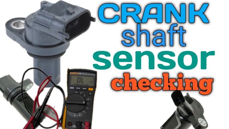
To bench test a crankshaft position sensor, first identify whether it is an inductive or Hall-effect sensor, then use the correct resistance, voltage, or signal-switching test for that design.
For U.S. car owners and DIY mechanics, bench testing a crankshaft position sensor can be a useful way to check a suspected sensor after it has been removed from the engine. The important part is choosing the test according to the sensor design. A two-wire variable-reluctance sensor usually generates its own AC signal and can often be checked for coil resistance. A Hall-effect sensor normally requires an external power supply and produces a digital switching signal instead.
Do not assume that every two-pin or three-pin crankshaft position sensor follows the same specification. American-market vehicles from Ford, GM, Stellantis, Toyota, Honda, Hyundai, Volkswagen, BMW, and other manufacturers use different sensor designs, supply voltages, pin arrangements, resistance specifications, and trigger wheels. Before applying power or selecting the ohms function on your multimeter, check the wiring diagram or service information for the exact year, make, model, engine, and sensor.
A bench test can reveal an open winding, shorted coil, missing output, or a Hall sensor that does not switch. It cannot fully reproduce the sensor’s installed operating conditions. Wiring faults, excessive air gap, a damaged reluctor wheel, heat-related failures, connector problems, and engine control module issues can all cause symptoms even when the removed sensor appears normal on the workbench.
Source: magaripoa.com
What You Need Before Bench Testing a Crankshaft Position Sensor
A successful bench test begins with information, not the multimeter. Find the sensor’s connector pinout, sensor type, expected supply voltage, and any resistance or output specifications provided for the vehicle. Factory service information is ideal, but a reliable vehicle-specific wiring diagram or component specification can also provide the required pin identification.
You will usually need a digital multimeter capable of measuring resistance, millivolts, AC voltage, and DC voltage. An oscilloscope is even more useful because it displays the shape and consistency of the sensor signal instead of averaging it into a single number.
For an active sensor, you may also need a regulated, current-limited DC power supply. Never assume that a three-wire sensor should receive 12 volts. Many automotive sensors operate from approximately 5 volts, while others use different supplies. Applying the wrong voltage can destroy the sensor.
Keep the removed sensor clean and dry. Inspect its connector pins, plastic body, mounting flange, sensing face, and wiring pigtail before beginning. Physical damage or heavy metallic debris may provide an explanation before electrical measurements are necessary.
Source: storage.googleapis.com
Digital multimeter
Use a meter that can accurately measure ohms, low AC voltage, and DC voltage.
Vehicle-specific specifications
Confirm the sensor type, pinout, expected resistance, supply voltage, and test procedure.
Test leads
Use probes or jumper leads that make secure contact without spreading or damaging connector terminals.
Regulated power supply
Use one only when bench testing an active sensor and only at the specified voltage.
Suitable trigger target
A ferrous steel target may work for many magnetic sensors, while some active sensors require a particular target geometry or magnetic pattern.
Oscilloscope
Optional but preferred when you need to confirm waveform quality rather than simply detect electrical activity.
Inspect the Sensor Before Connecting Test Equipment
Look closely for cracked plastic, damaged terminals, oil contamination inside the connector, corrosion, impact marks, or metal particles stuck to the sensing tip. A crankshaft sensor operates close to rotating engine components and may accumulate ferrous debris. Clean loose debris carefully without grinding, scraping, or damaging the sensing face.
Connector condition
Bent, pushed-back, oxidized, or loose terminals can produce an intermittent signal.
Sensor body
Cracks or evidence of contact with a reluctor wheel are reasons for closer inspection.
O-ring and mounting surface
Damage here can affect installation depth and therefore the operating air gap.
Identify Whether the Sensor Is Inductive or Hall Effect
Before learning how to bench test a crankshaft position sensor, determine how that specific sensor works. The two common categories are passive variable-reluctance sensors and active sensors such as Hall-effect designs.
A traditional inductive crankshaft position sensor contains a magnet and coil. As a ferrous reluctor tooth moves through the sensor’s magnetic field, the changing magnetic flux induces an alternating voltage in the coil. The sensor therefore does not need a separate power supply to create its basic output.
A Hall-effect sensor contains electronic circuitry. It normally receives a regulated power supply and ground, then switches a signal circuit as the appropriate trigger target passes the sensing face. Its output is commonly viewed as a digital square wave on an oscilloscope.
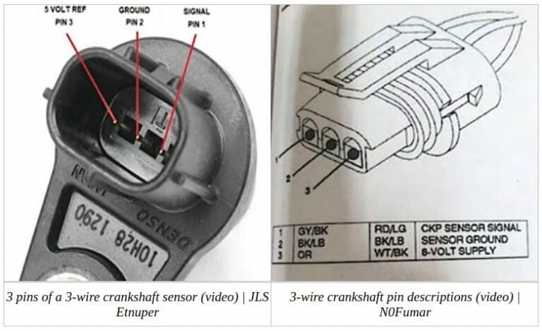
Wire count can provide a clue, but it is not a definitive identification method. Two-wire sensors are commonly passive inductive units, while three-wire sensors are often powered sensors. Shielding, specialized circuit designs, and manufacturer-specific arrangements create exceptions. Confirm the pinout before testing.
Source: autotoride.com
Two-wire sensor
Often a passive variable-reluctance design that generates an AC signal, but verify before assuming.
Three-wire sensor
Often an active sensor with power, ground, and signal circuits, although wire count alone is not proof.
Unknown sensor type
Do not perform a resistance test or apply external voltage until the design and terminals are confirmed.
Why Sensor Identification Matters
An ohmmeter sends a small test voltage through the component being measured. That is normally appropriate for a simple inductive coil when the service procedure allows it. It may be inappropriate for an active electronic sensor. Likewise, an inductive sensor does not need an external 5-volt or 12-volt supply simply to generate its normal magnetic pickup signal.
Wrong resistance test
May provide meaningless readings and can be unsuitable for active electronic sensors.
Wrong supply voltage
Can permanently damage an active sensor.
Wrong signal setting
An AC-generating sensor and a digital switching sensor should not be interpreted using the same meter expectations.
How to Bench Test a Two-Wire Inductive Crankshaft Position Sensor
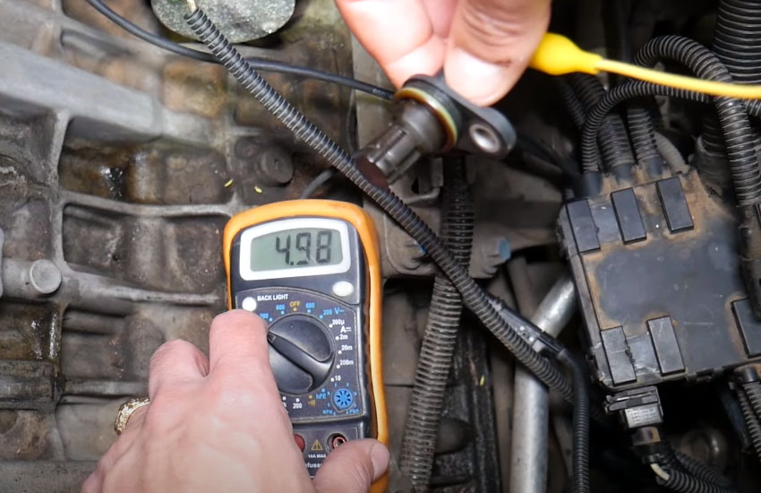
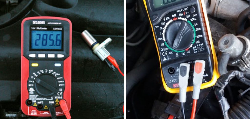
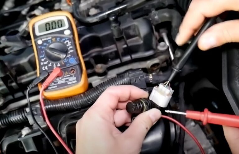
For a confirmed variable-reluctance sensor, begin with a resistance check if the vehicle manufacturer specifies one. This checks the continuity of the internal coil. After that, perform a dynamic output test by moving an appropriate ferrous target past the sensor and watching for generated AC voltage.
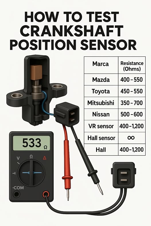
The exact resistance value varies substantially between sensor designs. Some references show several hundred ohms as common for certain sensors, but that is not a universal pass range. The correct comparison is the specification for your vehicle and sensor at the stated test conditions.
A resistance reading near zero can indicate a shorted winding. An open-loop or infinite reading can indicate an open winding. However, a resistance value within specification only shows that the coil has plausible continuity. It does not prove that the sensor creates a clean, correctly timed signal under actual engine speed, temperature, air-gap, and vibration conditions.
Source: safetyfic.com
Step 1: Confirm the sensor type
Verify from the wiring diagram or service procedure that the sensor is a passive variable-reluctance design.
Step 2: Set the meter to resistance
Choose an ohms range suitable for the expected sensor specification.
Step 3: Measure across the sensor terminals
Connect one meter lead to each specified sensor terminal without touching the probes together.
Step 4: Compare with the specification
Judge the reading against the service value rather than an internet-wide generic range.
Step 5: Select AC voltage
Use a low AC voltage or millivolt range if your meter provides one.
Step 6: Move a suitable target past the sensor
Pass an appropriate ferrous steel object briskly across the sensing face without striking it.
Step 7: Watch for generated voltage
A functioning inductive sensor should respond to changing magnetic conditions with an AC voltage pulse.
How to Interpret the Resistance Test
If the meter displays open circuit when the sensor should have measurable coil resistance, the internal winding or connection may be broken. A reading extremely close to zero may indicate a shorted winding. A plausible reading does not automatically mean the sensor is good, because output strength and intermittent faults remain untested.
OL or infinite resistance
Often indicates an open circuit when continuity should be present.
Near-zero resistance
May indicate an internally shorted winding.
Within specification
Confirms the static resistance check only; continue with an output test.
How to Perform the AC Output Test
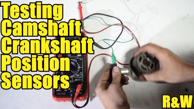
Connect the multimeter across the two sensor terminals and select AC voltage. Move the appropriate steel target repeatedly past the sensing tip. The meter may show only brief or small voltage changes because hand movement is much slower than an engine reluctor wheel. A scope is better for observing individual pulses.
Do not declare the sensor defective solely because a hand-operated bench test generates a lower voltage than a specification measured while cranking the engine. Inductive sensor voltage increases with the rate of magnetic-field change, so target speed, target shape, air gap, and meter response all affect the reading.
Repeatable pulse
A consistent response as the target passes the sensor supports basic sensor operation.
No response
Recheck the meter range, lead contact, target material, target distance, and sensor specification before condemning the part.
How to Bench Test a Three-Wire Hall-Effect Crankshaft Position Sensor
A Hall-effect crankshaft position sensor requires a different procedure because it contains active electronics. The usual bench test supplies the sensor with the correct voltage and ground, monitors the signal terminal, and moves the proper trigger target past the sensing face to see whether the output switches.
First obtain the exact pinout. Never determine power and ground by guessing based on connector position or wire color. Identify the power, ground, and signal terminals from reliable service information.
Set a regulated power supply to the voltage specified for the sensor. If available, use a current-limited supply so an accidental connection error is less likely to damage the sensor. Connect the sensor ground correctly and apply the specified power. Then measure the signal terminal relative to the correct ground.
Move the appropriate trigger target through the sensor’s detection zone. A properly configured active sensor should change its signal state as the target transitions past the sensing face. On an oscilloscope, this is typically visible as a high-to-low or low-to-high digital waveform.
Source: hitchesguide.com
Step 1: Obtain the pinout
Identify power, ground, and signal from exact vehicle or sensor documentation.
Step 2: Verify the required supply
Determine whether the sensor uses 5 volts, another regulated voltage, or a manufacturer-specific arrangement.
Step 3: Connect power and ground
Use a regulated supply and correct polarity.
Step 4: Monitor the signal
Set the multimeter to DC voltage or connect an oscilloscope between the signal and reference ground as specified.
Step 5: Move the correct trigger target
Pass the target through the sensing area while observing the output.
Step 6: Look for switching
The signal should repeatedly change state when the target enters and leaves the sensing zone.
Why a Hall Sensor May Need a Pull-Up Circuit
Some active sensor outputs do not independently drive a full high voltage. Instead, the output transistor pulls the signal low while the vehicle’s control module or circuit provides the pull-up voltage. If that design is tested on a workbench without the required pull-up circuit, the signal may appear dead even though the sensor is functional.
Do not add an arbitrary resistor or voltage simply because the signal does not move. Confirm the output circuit design first. The service manual, sensor datasheet, or a known-good vehicle circuit provides the best guidance.
Signal stuck low
Could indicate a sensor fault, incorrect target, wiring error, or inappropriate test circuit.
Signal stuck high
Could indicate missing switching, an unsuitable target, incorrect pin identification, or a circuit problem.
Signal switches repeatedly
Supports basic Hall sensor operation under the bench-test conditions.
A Multimeter May Hide the Digital Signal
A basic digital multimeter updates much more slowly than a crankshaft signal changes at engine speed. When the output switches rapidly, the meter may display an averaged or unstable voltage rather than distinct high and low values. A scope provides a much clearer view of pulse shape, amplitude, missing transitions, and electrical noise.
Slow manual triggering
Makes high and low states easier to observe with an ordinary multimeter.
Rapid triggering
Is better evaluated with an oscilloscope.
How to Read Your Bench Test Results
The best interpretation combines several observations rather than relying on one number. A passive sensor should have the specified electrical continuity and should generate a repeatable signal when its magnetic field is disturbed correctly. An active sensor should receive the correct supply, have a valid ground, and switch its signal when exposed to the correct target.
A failed resistance measurement on a sensor for which resistance testing is specified provides strong evidence of an internal electrical fault. A normal resistance reading is less conclusive because the sensor may still suffer from weak output, intermittent internal connections, heat sensitivity, or mechanical damage.
For a powered sensor, correct supply voltage alone says nothing about whether the switching electronics work. Conversely, a missing output on a poorly configured bench setup does not automatically condemn the sensor. Incorrect pin assignments, absent pull-up circuitry, insufficient target movement, or the wrong trigger material can all produce a false failure.
Source: educationsurvey.steelcase.com
Inductive sensor has open or shorted winding
The sensor is likely defective if the reading conflicts with the manufacturer’s specified resistance.
Inductive sensor has correct resistance but no output
Verify target speed, target material, air gap, meter range, and connections before replacing the sensor.
Hall sensor has no power
The bench setup or vehicle power circuit requires diagnosis before sensor output can be judged.
Hall sensor has power but does not switch
Confirm the pinout, ground, target type, pull-up requirements, and sensing distance before declaring failure.
Sensor passes every bench test
Continue diagnosis because the installed problem may involve wiring, connectors, reluctor damage, air gap, temperature, or another engine-management component.
A Simple Decision Sequence
If the sensor type is unknown, stop and identify it. If it is inductive and resistance testing is specified, check resistance first and then generated AC output. If it is an active sensor, confirm the pinout, apply only the specified supply, provide the correct ground and any required signal circuit, then check for switching. If the sensor passes, move the diagnosis back to the vehicle.
Fail static test
Recheck the specification and connections, then replace the sensor if the failure is confirmed.
Pass static but fail dynamic test
Verify the bench setup before deciding the sensor cannot produce a usable signal.
Pass all bench tests
Inspect the installed system instead of replacing the sensor based on symptoms alone.
Common Bench Testing Mistakes That Cause False Results
Crankshaft position sensors are easy to misdiagnose when a generic test procedure is applied to every sensor. The most common mistake is assuming the number of wires provides complete identification. Use wire count as a clue, then verify the actual circuit.
Another mistake is treating one resistance range as universal. Internal coil resistance depends on the sensor design and temperature, so a number that is normal for one engine may be wrong for another.
Testing only resistance is also insufficient. A coil can show continuity yet produce an inadequate or intermittent signal. Dynamic testing matters because the engine control module depends on a changing signal, not merely an intact coil.
Active sensors are especially vulnerable to incorrect bench setups. Reversed polarity, excessive supply voltage, incorrect grounding, or a missing pull-up circuit can create misleading results and may damage the component.
Source: harleydavidsonblog.com
Guessing the pinout
Connector position and wire color are not reliable enough for applying external power.
Using ohms on an unknown sensor
Identify the sensor technology before performing resistance checks.
Using one generic resistance specification
Always compare with data for the exact sensor application.
Expecting cranking voltage from a hand test
A slowly moved target may generate much less output than a rapidly rotating reluctor wheel.
Touching the sensor with the test target
Maintain a small gap instead of striking or scraping the sensing face.
Replacing a sensor after one ambiguous reading
Repeat the setup, confirm specifications, and use another test method when practical.
Do Not Apply 12 Volts Unless the Sensor Is Designed for It
Vehicle battery voltage is convenient, but convenience is not a valid reason to use it. An active sensor designed for a regulated lower-voltage supply can be damaged by direct battery voltage. Use the specified supply and correct polarity only.
Use a regulated supply
This allows precise voltage control during a powered bench test.
Use current limiting when available
Current limiting adds protection if a connection mistake occurs.
What a Bench Test Cannot Tell You
A bench test isolates the crankshaft position sensor from the rest of the vehicle, which is useful but also creates limitations. The removed sensor is no longer operating at its installed air gap, engine temperature, vibration level, cranking speed, or electrical load.
A damaged reluctor or tone wheel can produce an incorrect signal even when the sensor itself is healthy. Missing teeth where they should not be missing, excessive runout, damaged magnetic encoding, debris, or mechanical movement can disturb the waveform.
The wiring harness can also create symptoms that disappear on the workbench. Corroded terminals, poor pin tension, wiring rubbed through near the engine, voltage-drop problems, intermittent opens, or signal wires shorted to another circuit should be checked if the sensor passes.
Some sensors fail mainly when hot. A cold bench test may therefore look normal after the vehicle has stalled from heat soak. Temperature testing should only be performed within the component manufacturer’s allowable range. Avoid open flames or uncontrolled heating.
Air gap
Excessive distance between the sensor and target can weaken or eliminate the installed signal.
Reluctor condition
Mechanical or magnetic target damage can create a faulty waveform with a healthy sensor.
Harness condition
An off-vehicle test bypasses wiring and connector faults.
Heat-related failure
An intermittent sensor may pass at room temperature and fail after the engine compartment heats up.
Signal timing
A simple multimeter test does not verify crank-to-cam synchronization or exact tooth timing.
When an Oscilloscope Is the Better Test
Use an oscilloscope when the sensor produces a basic signal but the diagnosis remains uncertain. A scope can reveal signal amplitude, pulse spacing, digital high and low levels, dropouts, noise, abnormal tooth patterns, and changes that an averaging multimeter may conceal.
For the most meaningful diagnosis, waveform testing with the sensor installed and the engine cranking or running is often more informative than a bench test because it evaluates the sensor together with the real trigger wheel, air gap, wiring, and operating speed.
Inductive waveform
Normally appears as an alternating waveform whose amplitude changes with target speed and air gap.
Digital waveform
Normally appears as switching between defined high and low voltage states.
What to Do If the Crankshaft Position Sensor Passes
If the sensor behaves correctly on the bench, do not replace it solely because the engine has symptoms commonly associated with a crankshaft sensor. Return to the vehicle and test the complete circuit.
Check whether the engine control module sees engine speed while cranking with a scan tool. An RPM reading is useful evidence that the control module is receiving some form of crankshaft information, although it does not prove that the waveform is perfect.
Inspect the sensor connector, wiring path, power supply, ground, mounting surface, sensor air gap, and reluctor wheel. If the vehicle uses both crankshaft and camshaft position sensors, synchronization faults may require comparison of both signals with an oscilloscope.
Diagnostic trouble codes should also be interpreted in context. A crankshaft position sensor-related code identifies a circuit or signal problem detected by the control system; it does not automatically prove that the sensor itself is the failed component.
Check scan-tool RPM
Look for an engine-speed signal while cranking.
Inspect the harness
Look for damaged insulation, corrosion, loose terminals, and intermittent connections.
Verify installed air gap
Confirm that the sensor is fully seated and mounted according to specification.
Inspect the trigger wheel
Check for damage, contamination, excessive movement, or other conditions that alter the signal.
Scope the installed sensor
Use waveform testing when a multimeter cannot explain an intermittent or synchronization-related problem.
When to Get Professional Diagnostic Help
Professional diagnosis is worthwhile when the sensor requires a test circuit you cannot confidently reproduce, the wiring diagram is unavailable, the vehicle has intermittent stalling with no obvious cause, or accurate waveform analysis is necessary. Incorrectly powering an unknown sensor can turn a diagnostic problem into a damaged component.
Uncertain pinout
Do not experiment with power and ground connections.
Intermittent fault
A scope and recorded waveform can reveal problems that disappear during a basic bench test.
No-start with multiple codes
System-level diagnosis may be more efficient than testing individual parts in isolation.
Frequently Asked Questions About How to Bench Test a Crankshaft Position Sensor
Q
Can you bench test a crankshaft position sensor with only a multimeter?
Yes, many crankshaft position sensors can be checked at a basic level with a digital multimeter. A passive inductive sensor can often be tested for specified resistance and AC signal generation. A Hall-effect sensor can be monitored for signal switching if it is supplied with the correct power, ground, and any required signal circuitry.
A multimeter cannot display waveform shape as clearly as an oscilloscope, so it may miss brief dropouts, noise, uneven amplitude, or abnormal pulse spacing.
Q
What resistance should a crankshaft position sensor have?
There is no single resistance value that applies to every crankshaft position sensor. Some passive inductive sensors have resistance measurements in the hundreds of ohms, but the acceptable value depends on the specific design and test temperature.
Use the specification for the exact year, make, model, engine, and sensor. Do not use a resistance test on an unknown or active sensor unless the manufacturer specifically permits it.
Q
Can I test a three-wire crankshaft sensor without installing it?
Yes, a three-wire active sensor may be bench tested if you know the correct power, ground, signal pinout, required supply voltage, output circuit design, and trigger target. Apply only the specified supply and monitor the signal while moving the correct target through the sensing area.
Some sensors require a pull-up circuit or a particular magnetized target, so a simple three-wire hookup may not work for every design.
Q
Can a crankshaft sensor pass a bench test and still be bad?
Yes. An intermittent sensor may operate correctly when cold and fail when hot or vibrating. A bench test also removes the sensor from the actual air gap, reluctor wheel, wiring harness, connectors, and engine control module circuit.
If symptoms remain after the sensor passes, perform installed-system testing instead of assuming the bench result proves the entire crankshaft position system is healthy.
Q
Is an oscilloscope better than a multimeter for testing a crank sensor?
An oscilloscope provides more diagnostic information because it displays the electrical signal over time. It can reveal waveform shape, amplitude, switching levels, pulse spacing, noise, and intermittent dropouts.
A multimeter remains useful for preliminary checks such as resistance, supply voltage, ground, and basic output detection. For difficult intermittent faults or timing-related problems, a scope is usually the more informative tool.
✦ Wrapping Up
Conclusion
Knowing how to bench test a crankshaft position sensor starts with identifying the sensor technology. A confirmed inductive sensor can usually be checked for specified coil resistance and AC signal generation. A Hall-effect or other active sensor must be supplied and triggered according to its documented circuit design while its output is monitored for switching.
The most reliable approach is to avoid universal resistance numbers, guessed pinouts, and arbitrary supply voltages. Use specifications for the exact vehicle, verify the test setup, and remember that a sensor can pass on the bench while the installed system still has a wiring, air-gap, trigger-wheel, temperature, or synchronization problem.
💡 Key Takeaway
Identify the sensor type and exact pinout first, perform the manufacturer-appropriate static and dynamic tests, and if the sensor passes, continue diagnosis on the vehicle rather than replacing the part unnecessarily.
Ethan Brooks is an automotive writer at Auto News 7, covering car news, vehicle maintenance, new model updates, recalls, and practical buying guides. He focuses on clear, useful information that helps drivers understand their vehicles and make better ownership decisions.