To test a crankshaft position sensor with a scanner, read stored and pending codes, monitor the Engine RPM live-data PID while cranking, and look for a stable nonzero RPM signal. A continuous 0 RPM reading can indicate that the PCM is not receiving a usable crankshaft signal, but it does not prove the sensor itself is bad.
For drivers and DIY mechanics in the United States, a scan tool is usually the safest and fastest first diagnostic step when a vehicle cranks but will not start, stalls unexpectedly, or stores a crankshaft-position-related trouble code. Most 1996-and-newer gasoline passenger vehicles and light trucks sold in the U.S. use the standardized OBD-II diagnostic system, allowing a compatible scanner to retrieve diagnostic trouble codes and, when supported, display live engine-speed data.
The key is understanding what the scanner is actually telling you. It does not normally measure the crankshaft position sensor’s electrical output directly. Instead, it shows information calculated or reported by the powertrain control module, commonly called the PCM or ECM. If the scanner displays engine RPM while the starter is turning the engine, the control module is receiving enough crankshaft information to calculate engine speed. If RPM remains at zero, the diagnostic path should move toward the CKP sensor, its wiring, connector, power or ground where applicable, sensor air gap, reluctor wheel, battery condition, or related circuitry.
This guide explains how to test crankshaft position sensor with scanner data step by step, how to interpret common CKP trouble codes, what live-data readings mean, what a scanner cannot confirm, and what to test next before replacing parts.
Source: hitchesguide.com
What a Scanner Can Tell You About the Crankshaft Position Sensor
A scan tool tests the crankshaft position sensor indirectly. The CKP sensor monitors crankshaft rotation and position, while the PCM uses that signal to determine engine speed and crankshaft position. The scanner communicates with the PCM and displays information the module has received or calculated.
For a basic diagnosis, the most valuable live-data item is Engine RPM. Some enhanced scanners may also provide crank synchronization, camshaft and crankshaft synchronization status, misfire information, crankshaft variation data, or manufacturer-specific parameters. The exact data available depends on the vehicle and scan tool.
This distinction matters because seeing an RPM value does not prove that every CKP pulse is perfect. A sensor can occasionally produce a distorted or intermittent signal while the PCM still calculates an RPM value. Likewise, seeing 0 RPM does not prove that the physical sensor is defective. The signal may be missing because of an open wire, damaged connector, missing supply voltage, poor ground, excessive sensor-to-trigger-wheel gap, damaged reluctor wheel, or insufficient cranking speed.
Source: samarins.com
Scanner strength
It quickly shows codes and whether the PCM recognizes engine rotation.
Scanner limitation
A normal scan tool cannot display the raw CKP electrical waveform.
Best first PID
Engine RPM is usually the simplest live-data parameter for a crank-no-start CKP check.
Enhanced data
Some vehicles expose crank sync, cam/crank sync, or other manufacturer-specific parameters.
How the Crankshaft Position Sensor Works
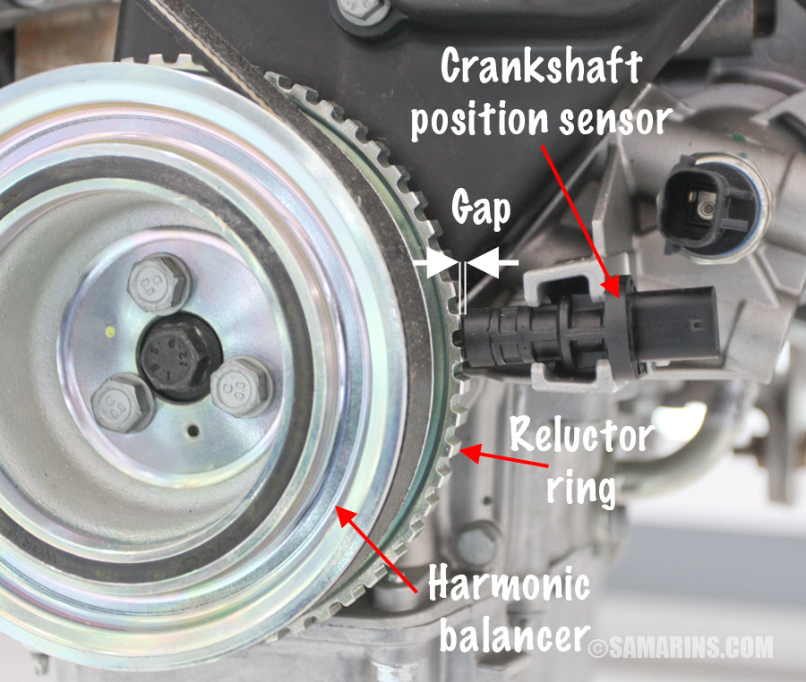
The crankshaft position sensor detects a trigger wheel, reluctor, tone ring, or another rotating reference associated with the crankshaft. The resulting signal allows the PCM to calculate crankshaft speed and position. Those calculations are important for functions such as ignition timing, fuel-injection timing, misfire monitoring, and engine synchronization.
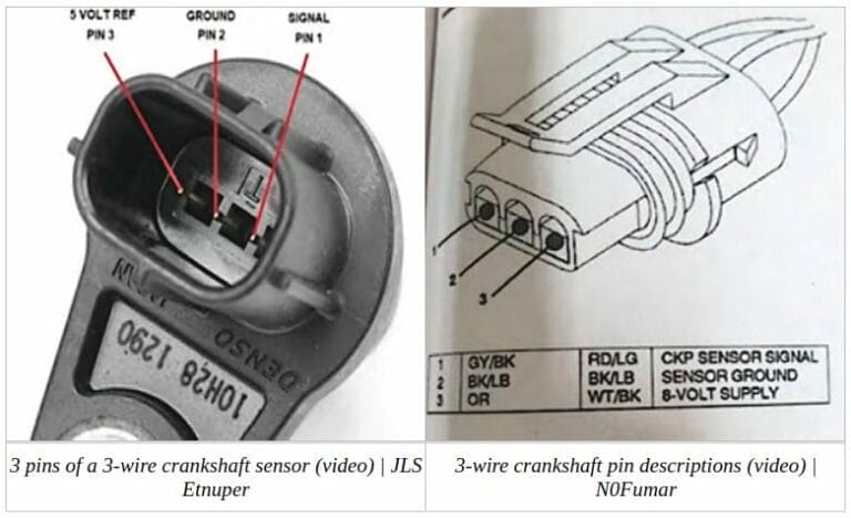
Vehicles may use inductive, Hall-effect, or other sensor designs. Because their electrical testing procedures differ, do not assume that wire count alone identifies the sensor type. Consult service information for the exact vehicle before performing resistance, voltage, or waveform testing.
CKP
Common abbreviation for crankshaft position sensor.
PCM or ECM
The control module that receives the crankshaft signal and calculates engine operating information.
Reluctor or tone wheel
The rotating target whose teeth or reference pattern are detected by the sensor.
How to Test Crankshaft Position Sensor With Scanner Step by Step
The basic procedure is to record codes first, open live data, monitor Engine RPM while cranking, and interpret the result without immediately condemning the sensor. Perform the test with the vehicle parked securely, the transmission in Park or Neutral as appropriate, and the parking brake applied.
Keep hands, clothing, cables, and the scanner lead away from belts, pulleys, cooling fans, and other moving components. If someone else needs to crank the engine while you watch data, communicate clearly before beginning.
Source: hitchesguide.com
Step 1: Connect the scanner
Locate the OBD-II data link connector, commonly under the driver’s side of the dashboard on U.S.-market passenger vehicles. Plug in the scanner and follow its startup procedure.
Step 2: Turn the ignition on
Switch the ignition to ON without starting the engine. Allow the scan tool to communicate with the PCM. Some push-button-start vehicles require a specific procedure to enter ignition-on mode.
Step 3: Scan all relevant codes
Read stored and pending diagnostic trouble codes before clearing anything. If the scanner provides freeze-frame information, record it because it can show operating conditions when a fault was detected.
Step 4: Open live engine data
Enter the PCM or engine live-data menu and select Engine RPM. If available, also select crank sync, cam/crank synchronization, battery voltage, or similar relevant parameters.
Step 5: Crank the engine
Watch the Engine RPM value while the starter turns the engine. Crank only as long as needed for the test and follow the vehicle manufacturer’s starting-system recommendations.
Step 6: Interpret the RPM reading
A stable nonzero RPM reading means the PCM is detecting engine rotation. A continuous 0 RPM reading means the PCM is not receiving or recognizing a usable engine-speed signal and the CKP circuit deserves further testing.
Step 7: Test intermittent symptoms
If the engine starts, graph or record Engine RPM if your scanner supports it. Watch for an unexplained RPM dropout at the same moment the engine hesitates or stalls.
What RPM Should You See While Cranking
There is no universal cranking RPM specification for every engine. Many passenger engines may crank somewhere in roughly the low hundreds of RPM, but battery condition, engine design, temperature, starter condition, oil viscosity, compression, and other factors affect speed. Use the service specification for the exact vehicle when a numerical limit matters.
For this scanner test, the first question is usually simpler: does the RPM PID remain at zero, or does it show a plausible and reasonably stable engine speed while cranking? A believable nonzero reading confirms that the PCM is receiving enough information to recognize crankshaft rotation.
Stable nonzero RPM
The PCM is receiving usable engine-speed information, so a total CKP signal loss is less likely at that moment.
Constant 0 RPM
Investigate the CKP sensor circuit, connector, power and ground where applicable, trigger wheel, installation, and cranking conditions.
RPM drops to zero during a stall
An intermittent CKP signal or circuit problem becomes an important possibility, especially if the dropout matches the symptom.
Crankshaft Position Sensor Codes to Check With the Scanner
A trouble code tells you what condition the control module detected; it does not tell you which component to replace. This is one of the most important rules when diagnosing a crankshaft position sensor.
Generic OBD-II CKP circuit codes commonly fall within P0335 through P0339. Depending on the vehicle, you may also encounter crankshaft variation, synchronization, misfire, or camshaft-to-crankshaft correlation codes. Manufacturer-specific definitions and diagnostic procedures can differ, so verify the exact code description for the year, make, model, and engine.
Do not erase the codes before writing them down. Clearing diagnostic memory too early can remove useful freeze-frame information and make an intermittent failure harder to reproduce.
Source: heartlandactors.com
P0335
Crankshaft Position Sensor A Circuit malfunction or a closely related circuit fault description.
P0336
Crankshaft Position Sensor A Circuit Range or Performance fault.
P0337
Crankshaft Position Sensor A Circuit Low Input fault.
P0338
Crankshaft Position Sensor A Circuit High Input fault.
P0339
Crankshaft Position Sensor A Circuit Intermittent fault.
P0315
Crankshaft position system variation not learned on vehicles that support this diagnostic strategy.
Does P0335 Mean the Crankshaft Sensor Is Bad
No. P0335 identifies a problem involving the crankshaft position sensor A circuit or signal as interpreted by the PCM. The sensor itself is only one possible cause.
Before replacing it, inspect the connector and harness and confirm that the sensor has the required electrical conditions. Also consider the reluctor wheel, sensor mounting, air gap, battery condition, starter speed, and any recent engine or transmission work that could have disturbed the sensor or trigger mechanism.
Possible sensor fault
The sensor may have failed internally or may become intermittent with temperature.
Possible wiring fault
An open, short, high resistance, damaged terminal, or poor connection can interrupt the signal.
Possible mechanical fault
A damaged or incorrectly positioned reluctor wheel can prevent a valid signal even when the sensor is functional.
How to Interpret Your Scanner Results
Treat scan-tool results as a decision point rather than a final diagnosis. The combination of symptoms, trouble codes, RPM data, synchronization information, and physical inspection is much more useful than any single reading.
A crank-no-start with 0 RPM deserves a different next step from a crank-no-start showing stable RPM. Likewise, an engine that runs normally cold but stalls hot should be tested while the symptom is actually occurring whenever that can be done safely.
Source: hitchesguide.com
0 RPM while cranking
The PCM is not reporting usable engine-speed information. Inspect the CKP circuit, verify power and ground when required, check connector integrity, examine the sensor installation and trigger wheel, and perform appropriate electrical testing.
Normal-looking RPM while cranking but engine will not start
A complete loss of CKP input becomes less likely. Continue diagnosis of fuel delivery, ignition, injector command, immobilizer operation, cam/crank synchronization, mechanical timing, and other vehicle-specific causes.
RPM suddenly drops to zero while running
If the RPM PID disappears at the same instant the engine stalls, investigate an intermittent CKP signal or circuit failure along with power-supply and PCM-related causes.
RPM is present but unstable
Do not assume the sensor is bad. Low battery voltage, starter problems, wiring faults, poor terminals, reluctor damage, incorrect sensor spacing, mechanical irregularities, or scanner update rate can affect what you see.
P0335 through P0339 with usable RPM
The fault may be intermittent, may occur only under certain conditions, or may involve signal quality rather than complete signal loss. Recording or graphing data can help.
Cam and crank synchronization shows No
Investigate both sensor circuits and mechanical timing according to manufacturer procedures instead of replacing one sensor based only on the synchronization status.
How to Find a Heat-Related CKP Failure
An intermittent crankshaft sensor can work when the engine is cold and fail after heat builds in the engine compartment. If the vehicle repeatedly stalls hot and then restarts after cooling, capture scanner data during the failure rather than testing only after the vehicle starts again.
Display or graph Engine RPM before, during, and immediately after the stall. If the engine is still mechanically rotating but the reported RPM abruptly disappears, the CKP signal path deserves close attention. Confirm the result with circuit or waveform testing before replacing the sensor.
Cold comparison
Record RPM behavior while the vehicle is operating normally.
Hot comparison
Repeat the test when the actual stall or no-start symptom occurs.
Record data
A scanner with recording or graphing makes a short signal dropout easier to spot.
What to Check When the Scanner Points to a CKP Problem
If the scanner repeatedly shows 0 RPM during cranking or records CKP-related faults, the next goal is to determine why the PCM is not receiving a valid signal. Replacing the sensor without these checks can waste money and leave the original fault unchanged.
Start with a visual inspection because damaged wiring and poor connections can create the same symptoms as a failed sensor. Follow the CKP harness as far as practical and look for chafing, melted insulation, oil or water contamination, loose connectors, bent terminals, corrosion, or wiring pulled tight by previous repairs.
Next, identify the exact sensor type from reliable service information. A Hall-effect sensor normally requires a power supply and ground in addition to its signal circuit, while an inductive sensor creates its own changing signal as the trigger wheel moves past it. Electrical procedures are therefore different.
Do not perform a generic resistance test on an unidentified sensor. Some active electronic sensors should be checked through supply, ground, signal, and waveform tests instead. When manufacturer specifications are unavailable or the circuit is unclear, professional diagnosis is safer than experimenting at the connector.
Source: safetyfic.com
Inspect the connector
Look for corrosion, moisture, oil contamination, bent pins, pushed-back terminals, or a connector that does not lock securely.
Inspect the harness
Check areas near the engine, exhaust, starter, transmission, brackets, and sharp edges for heat or abrasion damage.
Verify battery condition
A weak battery or slow starter can reduce cranking speed and complicate diagnosis. Address obvious cranking-system problems first.
Verify sensor power and ground
For sensors that require an external supply, use the vehicle wiring diagram and specified electrical test procedure.
Inspect sensor mounting
Confirm that the sensor is fully seated, securely mounted, and positioned according to vehicle specifications.
Inspect the reluctor or trigger wheel
Damage, movement, contamination, or incorrect mechanical alignment can corrupt the CKP signal.
Use an oscilloscope when needed
A scope can reveal missing pulses, distortion, amplitude problems, or intermittent waveform dropouts that an ordinary scan tool may not display.
Can a Scanner Confirm a Bad Crankshaft Position Sensor
A basic scanner usually cannot confirm the sensor itself as the failed component. It can establish valuable facts, such as whether CKP-related codes are stored and whether the PCM reports engine RPM during cranking, but those facts describe what the control module sees.
For example, 0 RPM can result from a failed sensor, an open signal wire, missing Hall-sensor power or ground, a connector problem, excessive air gap, a damaged trigger wheel, or another condition preventing the PCM from recognizing the signal.
A confident component-level diagnosis normally combines scan data with an inspection and the appropriate electrical or waveform checks for that specific vehicle.
Scanner evidence
Useful for codes, live RPM, synchronization status, and intermittent data loss.
Multimeter evidence
Useful for specified circuit voltage, ground, continuity, and certain sensor tests when the correct procedure is known.
Oscilloscope evidence
Useful for examining the actual signal pattern, consistency, timing, and dropouts.
Do You Need a Crankshaft Position Relearn After Replacement
Some vehicles require a crankshaft position variation relearn, crank relearn, or similar procedure after certain sensor, engine, PCM, or related repairs. Others do not require the same procedure. The requirement is vehicle-specific.
A basic code reader may not perform a relearn. The procedure can require a bidirectional or enhanced scan tool with manufacturer-specific functions. Follow the exact service procedure because some relearns require specific coolant temperature, transmission position, brake input, accessory status, or engine-speed conditions.
Do not confuse a relearn with a sensor test. A relearn teaches the PCM information needed for its diagnostic strategy; it does not repair a missing sensor signal, broken wire, damaged trigger wheel, or other physical fault.
Check service information
Determine whether the exact vehicle requires a CKP variation relearn.
Confirm scanner support
Look for manufacturer-specific service functions rather than assuming every OBD-II scanner can perform the procedure.
Repair faults first
Do not attempt to solve a genuine CKP circuit failure by repeatedly performing a relearn.
Common Mistakes When Testing a Crankshaft Position Sensor
The most common diagnostic mistake is treating a code description as a parts-replacement instruction. Scanner testing works best when it narrows the problem before more invasive tests begin.
Another mistake is relying on a single successful test when the complaint is intermittent. If a vehicle stalls only after driving for 30 minutes, checking RPM for ten seconds on a cold engine may not reproduce the fault. Whenever practical and safe, perform the test under the conditions that cause the symptom.
Also remember that scan data is processed information. Data refresh speed varies among tools and vehicles, and a brief raw-signal defect may not be obvious on a slowly updating numerical display. Graphing, recording, or oscilloscope testing may be necessary when the fault is short-lived.
Source: heartlandactors.com
Replacing the sensor from a code alone
Inspect and test the circuit before purchasing a replacement.
Clearing codes before recording them
Save stored, pending, and freeze-frame information first.
Assuming any nonzero RPM means the CKP system is perfect
Intermittent or distorted signals may still require further testing.
Ignoring a weak battery
Slow cranking and unstable system voltage can complicate diagnosis.
Testing only when the vehicle works normally
Intermittent failures should be captured during the actual symptom when possible.
Using resistance testing without identifying the sensor
Different CKP technologies require different electrical test procedures.
Working near moving components
Keep tools, leads, hands, clothing, and hair away from belts, pulleys, fans, and other rotating parts whenever the engine is cranking or running.
When to Get Professional Diagnostic Help
Professional help is sensible when scan data shows no CKP signal but the basic wiring inspection finds nothing obvious, when the sensor is difficult to access, when a wiring diagram is required, or when diagnosis requires an oscilloscope.
It is also worth escalating the diagnosis when crankshaft and camshaft correlation codes appear together, recent timing-system work has been performed, or mechanical timing and reluctor-wheel condition are possible causes. Replacing sensors without confirming the underlying fault can make these cases more expensive rather than less.
Electrical diagnosis
Seek help if power, ground, continuity, or signal tests cannot be performed confidently.
Waveform diagnosis
A technician with an automotive oscilloscope can evaluate raw CKP and CMP signals together.
Mechanical correlation
Timing or trigger-wheel faults may require mechanical inspection beyond ordinary scanner testing.
Frequently Asked Questions
Q
Can you test a crankshaft position sensor with an OBD2 scanner?
Yes, but the test is indirect. Use the scanner to check CKP-related trouble codes and monitor Engine RPM while cranking. If RPM remains at zero, the PCM is not recognizing usable engine-speed information. You still need further diagnosis to determine whether the cause is the sensor, wiring, connector, supply circuit, ground, trigger wheel, or another problem.
Q
What should the scanner show if the crankshaft position sensor is working?
During cranking, you should normally see a plausible nonzero Engine RPM value if the PCM is receiving enough crankshaft information to calculate speed. The exact RPM varies by vehicle and conditions, so use manufacturer specifications if you need a numerical pass or fail limit.
If an enhanced scanner provides a crank synchronization parameter, its status can provide additional information, but availability and terminology vary among manufacturers.
Q
Can a crankshaft position sensor be bad even if RPM shows on the scanner?
Yes. A sensor can have an intermittent, weak, or distorted signal while still providing enough information for the PCM to calculate RPM at some times. If symptoms are intermittent, record or graph RPM during the actual failure and consider waveform testing.
Q
Can a bad crankshaft position sensor cause a crank-no-start?
Yes. If the PCM loses the crankshaft information it needs for engine synchronization, some vehicles can crank normally without starting. However, a crank-no-start has many other possible causes, including fuel, ignition, immobilizer, electrical, mechanical-timing, and camshaft-signal problems.
Q
Can you test the CKP sensor without removing it?
Often, yes. The scanner portion of the diagnosis is performed with the sensor installed. Depending on sensor design and vehicle access, power, ground, signal, and waveform checks may also be performed with the sensor connected using approved back-probing or breakout methods. Follow the vehicle’s service information to avoid damaging terminals or wiring.
✦ Wrapping Up
Conclusion
The simplest way to understand how to test crankshaft position sensor with scanner data is to focus first on codes and live Engine RPM. Record stored and pending faults, open live data, and watch RPM while the engine cranks. A believable nonzero RPM value means the PCM is recognizing crankshaft rotation at that moment. A continuous 0 RPM reading means the CKP signal path requires further diagnosis.
Do not replace the crankshaft position sensor based only on P0335, another CKP code, or a zero-RPM reading. Inspect the connector and harness, verify the required electrical circuits, consider battery and starter condition, and check the sensor installation and reluctor wheel. If those checks are inconclusive, the appropriate multimeter tests or an oscilloscope can separate a failed sensor from wiring and mechanical faults.
For U.S. DIYers working with an OBD-II vehicle, this scanner-first approach keeps the diagnosis efficient while reducing unnecessary parts replacement. Vehicle-specific service information remains the final authority for pin identification, specifications, sensor type, relearn requirements, and electrical procedures.
💡 Key Takeaway
Connect the scanner, record the codes, monitor Engine RPM while cranking, and use a zero or intermittent RPM signal as a reason to test the CKP system further rather than as automatic proof that the sensor is bad.
Ethan Brooks is an automotive writer at Auto News 7, covering car news, vehicle maintenance, new model updates, recalls, and practical buying guides. He focuses on clear, useful information that helps drivers understand their vehicles and make better ownership decisions.