To test a crankshaft position sensor with an oscilloscope, identify the sensor type and signal wire, connect the scope without damaging the circuit, crank or run the engine, capture the waveform, and check its voltage, shape, spacing, reference gap, and consistency against vehicle-specific specifications or a known-good waveform.
For drivers and DIY technicians in the United States, oscilloscope testing is one of the most useful ways to diagnose a suspected crankshaft position sensor because it shows what the sensor is doing while the engine is actually turning. A digital multimeter can reveal an open circuit, missing supply voltage, or some basic resistance and voltage problems, but it normally cannot show individual crankshaft pulses, intermittent dropouts, irregular tooth spacing, or a damaged reluctor pattern with the same clarity.
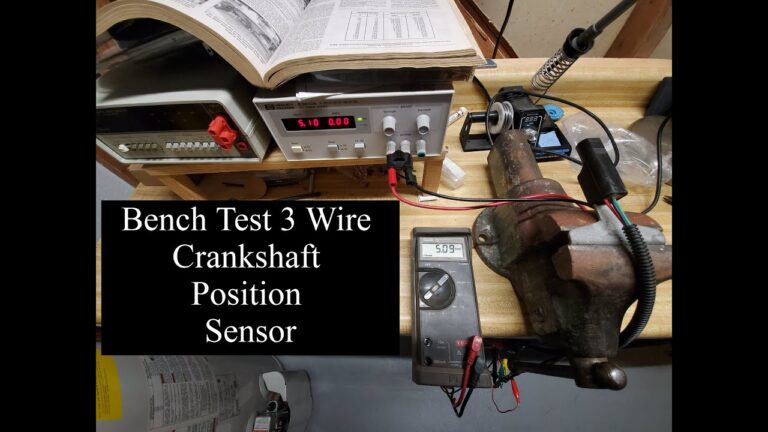
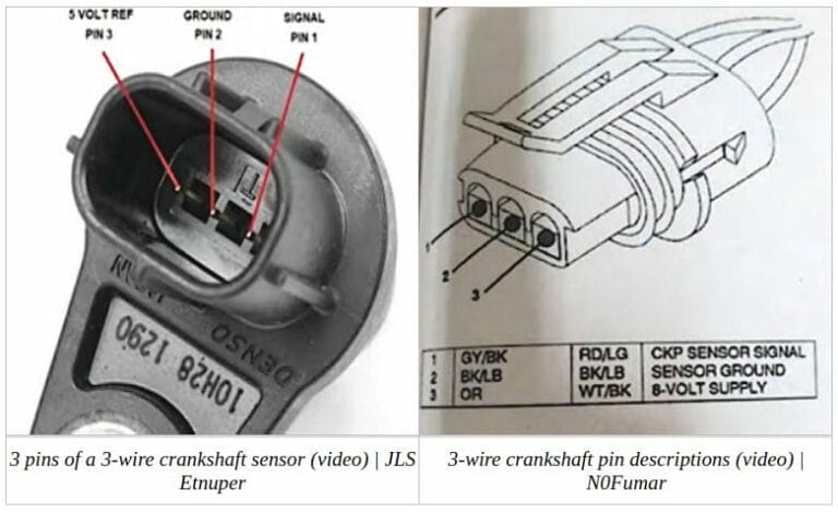
The procedure is not identical on every U.S.-market vehicle. Crankshaft position sensors can be inductive, Hall effect, or another electronically conditioned design, and their wiring and expected waveform differ. Before connecting test equipment, use the wiring diagram or service information for the exact year, make, model, engine, and sensor circuit. This is especially important because assuming that every two-wire or three-wire sensor operates the same way can lead to a false diagnosis or an unsafe scope connection.
Source: picoauto.com
What an Oscilloscope Test Tells You About a Crankshaft Position Sensor
An oscilloscope displays voltage against time. When connected to the crankshaft position sensor circuit, it lets you see each electrical event generated as the crankshaft trigger wheel or reluctor passes the sensor.
The engine control module uses the crankshaft position signal as a primary reference for crankshaft speed and position. Depending on the vehicle, that information contributes to ignition timing, fuel injection timing, misfire monitoring, starting strategy, and synchronization with the camshaft position signal.
This is why waveform testing provides information that a simple static resistance check cannot. You can determine whether a signal exists, whether the pulses are evenly formed, whether the expected reference gap is visible, whether the signal disappears intermittently, and whether its behavior changes as engine speed changes.
A waveform that looks abnormal can also point beyond the sensor. A damaged trigger wheel, excessive sensor-to-wheel air gap, loose crankshaft components, wiring resistance, shorts, poor connections, or electrical interference may distort the CKP signal even when the sensor itself is capable of operating.
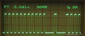
Source: samarins.com
Signal presence
The scope shows whether the CKP circuit produces a usable signal while the crankshaft rotates.
Waveform quality
You can inspect pulse shape, amplitude, spacing, noise, missing pulses, and unexpected voltage changes.
Reference pattern
Many trigger wheels contain a deliberate missing-tooth or distinctive reference feature that should recur consistently.
Intermittent faults
A captured waveform can reveal brief signal losses that may be missed by a digital multimeter.
Why a Multimeter and an Oscilloscope Give Different Information
A multimeter is useful for checking supply voltage, ground integrity, resistance on appropriate sensor designs, and broad voltage behavior. However, it averages or samples electrical activity in a way that may hide individual CKP pulses. An oscilloscope displays those pulses directly, making it much better suited to evaluating signal integrity.
Do not perform a resistance test simply because the sensor has a familiar connector. Some powered electronic sensors can be damaged or incorrectly diagnosed with inappropriate resistance testing. Identify the sensor design and follow vehicle-specific procedures first.
Identify the Crankshaft Position Sensor Type Before Testing
The most important preparation step is determining what type of CKP sensor the vehicle uses. Do not diagnose a waveform until you know what kind of signal should be present.
Two common designs are variable-reluctance inductive sensors and Hall effect sensors. Connector pin count can provide a clue, but it should not be treated as absolute identification. Wiring diagrams and manufacturer service information are more reliable.
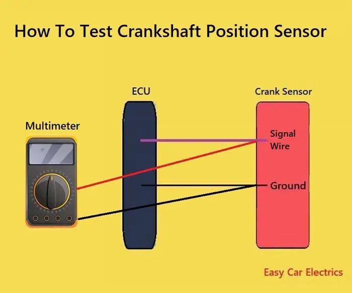
Source: artofit.org
Inductive sensor
Typically generates its own alternating voltage as reluctor teeth move through its magnetic field. Signal amplitude changes significantly with rotational speed.
Hall effect sensor
Requires electrical power and ground and normally sends a digitally switched signal to the engine control module.
Vehicle-specific designs
Some circuits use different bias voltages, differential or floating arrangements, integrated electronics, or signal strategies that require manufacturer-specific information.
What an Inductive CKP Waveform Looks Like
A conventional inductive crankshaft sensor usually produces an alternating waveform with positive and negative portions. As engine speed increases, the generated voltage normally increases because the trigger wheel moves through the magnetic field more quickly.
During cranking, the waveform will therefore have lower amplitude than it normally has with the engine running at higher rpm. This is one reason a universal minimum voltage number is unreliable across different vehicles.
What a Hall Effect CKP Waveform Looks Like
A Hall effect crankshaft sensor generally produces a digital waveform that switches between low and high voltage states as trigger-wheel features pass the sensor. Many systems operate around a 0-to-5-volt signal range, but that should not be assumed for every vehicle.
With a Hall sensor, waveform quality depends not only on the sensor but also on its power supply, ground, signal circuit, trigger wheel, and control-module circuitry. Check those supporting circuits if the signal is missing or does not reach its expected voltage levels.
What You Need Before Testing the CKP Sensor
Prepare the vehicle and test equipment before making connections. A correct waveform is useful only if the oscilloscope is connected to the correct circuit and configured appropriately.
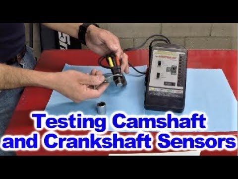
You should have an automotive-capable oscilloscope, suitable probes or back-probing leads, the vehicle wiring diagram, and preferably manufacturer specifications or a known-good reference waveform. A scan tool is also useful because diagnostic trouble codes and live engine-speed data can provide additional context.
Keep test leads, clothing, hands, and equipment clear of the serpentine belt, pulleys, cooling fans, exhaust components, and other moving or hot parts. An electric cooling fan may operate unexpectedly even when you are concentrating on a different circuit.
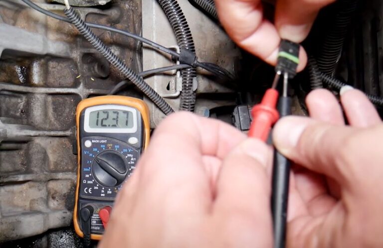
Source: hitchesguide.com
Automotive oscilloscope
Use a scope and probes suitable for automotive voltage levels and the circuit being measured.
Wiring information
Identify the exact signal, power, ground, and sensor circuit configuration before connecting a probe.
Back-probing equipment
Use methods that do not spread terminals or damage insulation whenever possible.
Scan tool
Use stored codes and rpm data to supplement waveform findings rather than diagnosing from a fault code alone.
Known-good information
A waveform from the same engine family under comparable conditions is far more useful than relying on a generic picture.
How to Test Crankshaft Position Sensor With Oscilloscope Step by Step
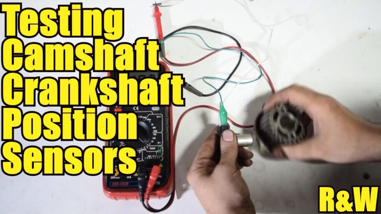
The basic procedure is to capture the CKP signal while the engine is cranking or running, then evaluate the waveform against the expected pattern. The correct probe connection depends on the sensor and circuit design, so the wiring diagram takes priority over generic instructions.
For a cranking no-start diagnosis, capturing several seconds of cranking is usually enough to establish whether the CKP signal is present and consistent. If the engine runs, viewing the signal at idle and under controlled rpm changes may reveal faults that do not appear during cranking.
Source: youtube.com
Step 1: Check trouble codes and symptoms
Record diagnostic trouble codes and relevant symptoms before disconnecting anything. CKP-related codes can include P0335 through P0339 on many OBD-II vehicles, although code definitions and diagnostic logic vary.
Step 2: Locate the CKP sensor and identify its circuit
Use the vehicle wiring diagram to identify the CKP connector, signal circuit, supply circuit if present, ground, and whether the sensor output is referenced or floating.
Step 3: Inspect the wiring first
Check for damaged insulation, oil contamination, connector corrosion, loose terminals, harness contact with moving parts, and evidence of previous repairs.
Step 4: Connect the oscilloscope
Back-probe the designated signal circuit according to the wiring diagram. Connect the reference or ground lead only where appropriate for the scope and circuit configuration.
Step 5: Choose a safe starting voltage range
Set a range wide enough that the expected waveform will not exceed the display. Refine the range after observing the signal.
Step 6: Set the time base
Choose a time scale that displays enough crankshaft pulses to recognize the repeating pattern and reference gap rather than zooming in on only one pulse.
Step 7: Crank or run the engine
Start waveform capture, then crank the engine for several seconds or operate it under the conditions required by the diagnostic procedure.
Step 8: Freeze and inspect the waveform
Look for appropriate amplitude, clean pulse formation, regular spacing, the expected reference feature, and any dropouts or distortions.
Step 9: Compare with known-good data
Compare the waveform with manufacturer service information or a known-good capture from the same engine and similar rpm whenever possible.
Step 10: Verify the cause before replacing the sensor
If the waveform is abnormal, test the sensor’s supporting circuits and inspect sensor mounting, air gap, trigger wheel, wiring, and connectors before condemning the CKP sensor.
How to Connect a Scope to an Inductive CKP Sensor
An inductive CKP circuit may be referenced to ground or may operate as a floating differential circuit. That distinction matters. On a referenced circuit, the signal may be measured relative to the specified reference. A floating two-wire circuit may require both channels or an appropriate differential measurement method to observe both sides correctly.
Do not automatically ground one side of an unknown floating sensor circuit through an earth-referenced test instrument. Confirm the oscilloscope’s input and ground arrangement and the vehicle circuit before connecting it. If you are uncertain about the connection method, use the oscilloscope manufacturer’s automotive guidance or have a qualified technician perform the test.
How to Connect a Scope to a Hall Effect CKP Sensor
Use the wiring diagram to identify the Hall sensor’s signal wire, power feed, and ground. Back-probe the signal circuit while leaving the sensor connected so it operates under normal electrical load. Measure the signal relative to the specified sensor or circuit ground.
If there is no switching waveform, do not replace the sensor immediately. Verify that its required supply voltage and ground are present and stable. A perfectly functional Hall sensor cannot produce the expected output if its power or ground circuit is missing.
How to Read a Crankshaft Position Sensor Waveform
Do not judge a CKP waveform by voltage alone. A useful diagnosis considers amplitude, pulse shape, spacing, periodic reference features, consistency over multiple revolutions, and behavior as engine speed changes.
Many trigger wheels contain one or more intentionally missing teeth or another distinctive pattern that allows the engine control module to recognize crankshaft position. The resulting wider waveform interval is expected and should repeat at the same point in every revolution or specified cycle. Do not mistake a designed reference gap for a missing signal.
Conversely, a single abnormal pulse appearing at an unexpected point can be significant. A damaged or contaminated reluctor tooth, excessive air gap, wheel movement, sensor damage, or electrical fault may produce an irregular waveform.
Source: picoauto.com
Uniform pulses
Normal trigger teeth should generally produce a consistent repeating pattern under steady rotational conditions.
Reference gap
A deliberately wider interval or distinctive pattern should repeat predictably if the trigger wheel uses a missing-tooth reference.
Stable amplitude
At a reasonably steady rpm, major unexplained changes in signal height deserve investigation.
No random dropouts
Unexpected loss of one or more pulses can indicate a sensor, wiring, connection, air-gap, or trigger-wheel problem.
Appropriate switching
A Hall sensor should transition cleanly between its designed low and high voltage levels.
Reading an Inductive Sensor Waveform
An inductive sensor waveform generally crosses above and below its reference level. Each passing tooth changes the magnetic field and creates a voltage. The signal becomes stronger as rotational speed rises, so amplitude differences between slow cranking and running should be expected.
If the waveform is uniformly weak, possible causes include low cranking speed, an excessive sensor air gap, contamination, sensor degradation, circuit resistance, or another mechanical or electrical condition. Compare the result under equivalent rpm and test conditions before drawing a conclusion.
Reading a Hall Effect Sensor Waveform
A Hall sensor produces a switched digital pattern rather than the conventional sine-like output of a variable-reluctance sensor. Concentrate on high and low voltage levels, clean edges, consistent pulse widths and spacing, and reliable switching throughout the capture.
A signal that never changes state can indicate a failed sensor, missing power or ground, a signal-circuit problem, incorrect sensor-to-trigger relationship, or another system fault. Test those possibilities rather than diagnosing the sensor from waveform shape alone.
Good vs Bad CKP Waveform: What the Patterns Can Mean
A good CKP waveform is repeatable. Normal teeth produce an orderly pattern, intentional reference features occur at predictable intervals, and the signal remains present as the engine turns. A bad waveform is usually identified by an unexplained departure from that repeating pattern rather than by one universal voltage limit.
Use the following patterns as diagnostic clues rather than automatic proof of a failed sensor. The same visible defect can have several possible causes.
Source: storage.googleapis.com
No waveform
Check whether the crankshaft is actually rotating, then investigate sensor power and ground where applicable, open circuits, shorts, connector faults, sensor failure, and the measurement connection.
Intermittent missing pulses
Inspect the harness and terminals, sensor mounting, trigger wheel, air gap, and sensor operation. Heat or vibration can also expose intermittent electrical faults.
One abnormal pulse every revolution
A repeating defect at the same crankshaft location may justify inspecting the reluctor or trigger wheel for a damaged, bent, contaminated, or incorrectly positioned feature.
Hall signal does not reach expected high or low level
Check supply voltage, sensor ground, circuit loading, connector condition, shorts, resistance, and the sensor itself.
Heavy noise or irregular spikes
Investigate poor test connections, damaged wiring, grounding problems, electromagnetic interference, and circuit faults before replacing components.
Why the Missing-Tooth Gap Is Usually Normal
A missing-tooth pattern is intentionally built into many crank trigger wheels. The longer interval gives the engine control module a position reference. On an inductive waveform, the teeth immediately around this gap can also create distinctive voltage behavior because the magnetic transition differs from ordinary adjacent teeth.
The key is repetition. A designed reference pattern appears predictably. Random missing or malformed events elsewhere in the waveform are more suspicious.
What to Do If the Crankshaft Sensor Waveform Looks Bad
An abnormal waveform tells you there is a problem with the signal or its generation, but it does not identify the failed component by itself. Perform supporting checks before installing a new CKP sensor.
Begin with wiring and connector condition because an open circuit, high resistance, poor terminal contact, or short can alter or eliminate an otherwise valid sensor signal. For a powered sensor, confirm the required supply and ground under operating conditions.
Next inspect the sensor installation and trigger system. Excessive air gap, metal debris on a magnetic sensor, a damaged reluctor, loose components, incorrect installation, or abnormal crankshaft or flywheel movement can affect the waveform.
If the waveform appears correct at the sensor but the engine control module does not recognize engine speed, compare the signal at another accessible point in the circuit when the manufacturer’s diagnostic procedure allows it. A difference can indicate a wiring or terminal problem between those locations.
Source: picoauto.com
Check power and ground
Required on powered CKP designs such as many Hall effect sensors.
Inspect connector terminals
Look for looseness, corrosion, contamination, pushed-back terminals, or poor contact.
Inspect harness routing
Check for chafing, melted insulation, stretched wires, previous repairs, and proximity to interference sources.
Check sensor mounting
Confirm that the sensor is secure and correctly positioned.
Inspect the trigger wheel
Look for physical damage, contamination, looseness, incorrect positioning, or abnormal movement where inspection is practical.
Compare hot and cold operation
If the symptom is temperature-dependent, capture waveforms under the conditions when the fault actually occurs.
When to Compare the Crankshaft and Camshaft Signals
If the individual CKP waveform looks healthy but the vehicle has crankshaft-to-camshaft correlation codes, difficult starting, timing-related faults, or suspected mechanical timing problems, capturing CKP and camshaft position signals simultaneously can provide more information.
The relative position of the two waveforms can then be compared with vehicle-specific known-good data. A shifted relationship may be associated with mechanical timing, trigger-wheel positioning, variable valve timing, or sensor relationship issues. A generic waveform cannot establish correct cam-to-crank synchronization for every engine.
Common Mistakes When Testing a Crankshaft Position Sensor
Most CKP oscilloscope mistakes come from testing the wrong circuit, assuming the sensor type, using an unsuitable ground connection, or interpreting a generic waveform as a universal specification.
Another common mistake is replacing the sensor as soon as the waveform looks unusual. The CKP signal is produced by an electrical sensor interacting with a mechanical trigger, then traveling through wiring and connectors to the control module. A fault anywhere along that chain can alter the waveform.
Assuming pin count identifies the sensor
Use service information instead of relying solely on whether the connector has two or three wires.
Using arbitrary voltage limits
Expected amplitude depends on sensor design, engine speed, circuit configuration, air gap, and vehicle specifications.
Mistaking a reference gap for a failure
A deliberate missing-tooth pattern is normal on many engines.
Ignoring cranking speed
A weak battery or starter problem can reduce cranking speed and therefore reduce the output of an inductive sensor.
Using unsafe grounding
Understand whether the CKP circuit is ground-referenced or floating and whether the oscilloscope channels share a common ground.
Damaging connector terminals
Avoid forcing oversized probes into terminals. Use appropriate back-probing tools.
Testing beside moving components
Secure all leads away from belts, fans, pulleys, hot exhaust parts, and other hazards before cranking or starting the engine.
How to Confirm the Repair
After repairing the actual fault, repeat the oscilloscope test under approximately the same operating conditions that produced the original problem. The waveform should now be stable and consistent with the expected pattern for that engine.
Clear diagnostic trouble codes only after recording anything needed for diagnosis, then operate the vehicle according to the applicable service procedure and verify that relevant codes do not return. If the original symptom appeared only when hot, during extended cranking, or at a particular engine speed, reproduce those conditions safely before considering the problem resolved.
Also check scan-tool engine-speed data when useful. During cranking, an rpm value that is consistently recognized by the control module can support the finding that a usable CKP signal is reaching the system, although scan data by itself does not prove that every feature of the waveform is correct.
Repeat the capture
Use comparable rpm and test settings so the before-and-after waveforms can be meaningfully compared.
Verify the symptom
Confirm that the no-start, stall, intermittent cutout, or other original complaint has actually been corrected.
Recheck codes
Make sure CKP or correlation faults do not return after the appropriate operating cycle.
Frequently Asked Questions About How to Test Crankshaft Position Sensor With Oscilloscope
Q
What should a good crankshaft position sensor waveform look like?
A good waveform should be stable and repeatable for the sensor design and operating condition. An inductive sensor normally produces an alternating analog waveform, while a Hall effect sensor usually produces a switched digital waveform. Pulse spacing should follow the trigger-wheel pattern, intentional reference gaps should repeat predictably, and random dropouts should not be present.
The best comparison is manufacturer information or a known-good waveform from the same engine under similar rpm and operating conditions.
Q
What voltage should a crankshaft position sensor show on an oscilloscope?
There is no single correct CKP voltage for every vehicle. Inductive sensor amplitude changes with engine speed and design, while powered digital sensors operate according to their circuit specifications. Some Hall effect systems switch around a 0-to-5-volt range, but other designs exist.
Use the specification for the exact vehicle rather than treating a generic voltage value as a pass-or-fail standard.
Q
Can you test a crankshaft position sensor while cranking the engine?
Yes. Cranking is especially useful when diagnosing an engine that will not start. Capture several seconds of CKP activity while the starter rotates the engine, then inspect whether the waveform is present, correctly shaped, and consistent.
Remember that an inductive sensor normally generates less voltage during slow cranking than it does at higher running speeds.
Q
Can a crankshaft sensor have a good waveform and still cause a problem?
An intermittent fault may disappear during a short test, so a normal capture does not rule out every CKP-related problem. If the complaint happens only when the engine is hot, after vibration, during a long drive, or at a particular rpm, capture the signal when those conditions occur.
Also consider faults farther along the circuit and timing-related problems. If the CKP signal is correct at the sensor but does not reach the control module correctly, wiring or terminal faults may still be present.
Q
Does a P0335 code automatically mean the crankshaft position sensor is bad?
No. A CKP-related trouble code identifies a problem detected in the crankshaft position signal or associated diagnostic logic, not necessarily a defective sensor. Wiring faults, poor connectors, power or ground problems, trigger-wheel damage, excessive air gap, mechanical issues, and other conditions can produce CKP-related codes.
Use the code as the beginning of the diagnostic process and verify the circuit and waveform before replacing parts.
✦ Wrapping Up
Conclusion
Learning how to test crankshaft position sensor with oscilloscope comes down to three things: identify the sensor and circuit correctly, capture the signal under the conditions where the problem occurs, and evaluate the complete waveform instead of focusing on one voltage number. An inductive CKP sensor normally produces an analog alternating signal, while a Hall effect sensor generally produces a digital switching signal.
A clean waveform does more than confirm that voltage exists. It lets you inspect individual pulses, reference gaps, amplitude consistency, switching quality, and intermittent dropouts. If the waveform is abnormal, confirm wiring, connector condition, sensor power and ground where applicable, mounting, air gap, and trigger-wheel condition before deciding that the sensor itself needs replacement.
💡 Key Takeaway
Start with the exact vehicle wiring diagram, identify the CKP sensor type, capture several crankshaft revolutions with the oscilloscope, and compare the waveform with vehicle-specific or known-good data before replacing any component.
Ethan Brooks is an automotive writer at Auto News 7, covering car news, vehicle maintenance, new model updates, recalls, and practical buying guides. He focuses on clear, useful information that helps drivers understand their vehicles and make better ownership decisions.