Read knock sensor data by comparing knock retard, ignition timing, engine load, RPM, and related signals under the same conditions.
If you are diagnosing a gasoline vehicle in the United States, a scan tool can give you useful clues about how the engine control module is responding to possible knock. The key is to read the knock-related data in context rather than looking for one universal number. Vehicle manufacturers use different knock-control strategies, and many deeper knock parameters are manufacturer-specific.
To understand how to read knock sensor data, first identify what your scan tool is actually displaying. A parameter called knock retard may show timing removed by the engine control module, while a knock sensor voltage parameter may show a processed sensor signal. Those are not interchangeable. A good diagnosis compares the knock-related value with RPM, load, ignition timing, fuel trims, temperature, and misfire information while noting exactly when the change occurs.
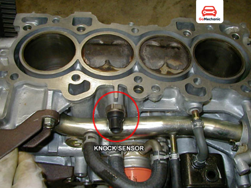
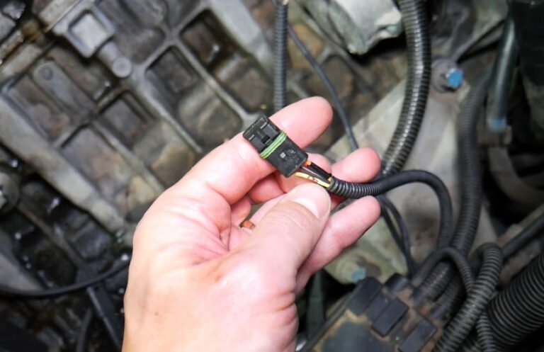
Source: qaqooking.wiki
What Knock Sensor Data Actually Tells You
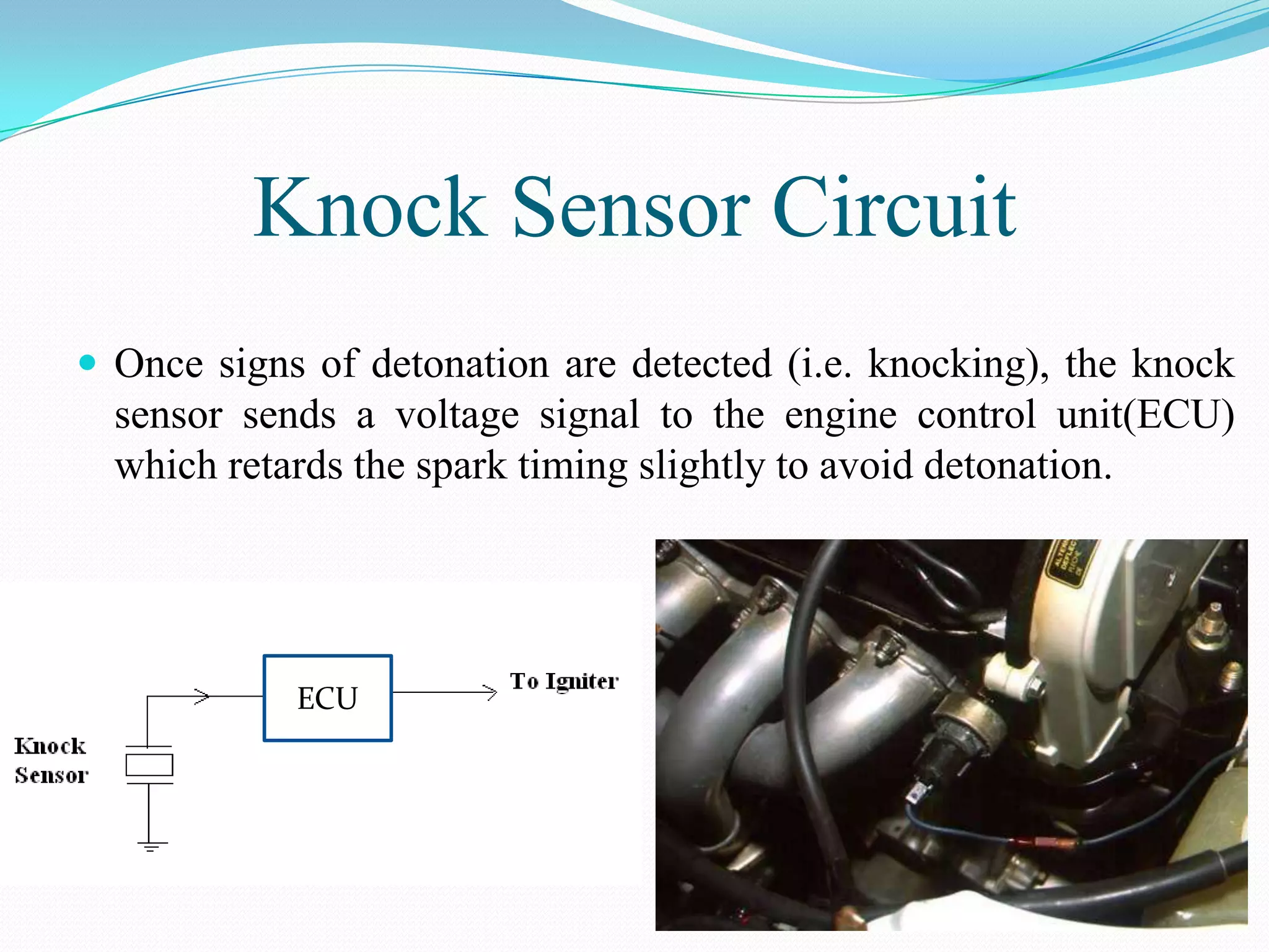
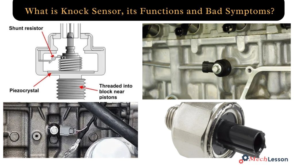
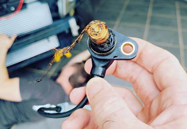
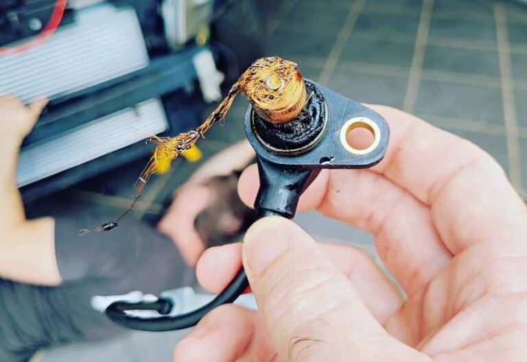
A knock sensor detects engine-block vibrations associated with abnormal combustion and sends a signal to the engine control module. Modern knock sensors commonly use a piezoelectric element that converts mechanical vibration into an electrical signal. The control system then analyzes that signal and can adjust ignition timing when its knock criteria are met.
When learning how to read knock sensor data, separate the physical sensor signal from the value calculated by the control module. A scan tool may show the sensor voltage, a knock activity state, a knock count, knock retard, learned knock correction, or another manufacturer-specific parameter. Each value answers a different question.
For example, knock retard generally describes how much ignition timing the control module has removed in response to its knock-control strategy. It does not necessarily mean the engine is currently producing the same amount of actual combustion knock. The control module may also use temperature, load, engine speed, cylinder information, and other inputs when deciding how to control ignition timing.
This distinction is one of the most important parts of reading live data. A scan tool reports information provided by the vehicle control module. It does not independently prove that a sensor is physically measuring the condition you suspect.
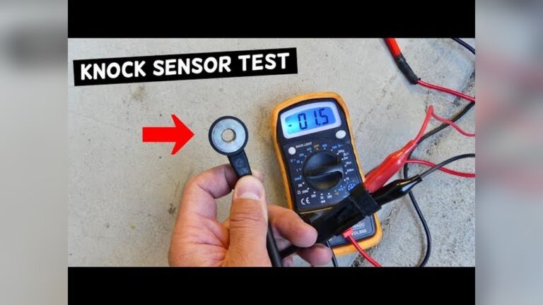
Source: slideshare.net
Knock sensor voltage
This may represent a raw or processed electrical signal from the knock sensor, depending on the vehicle and scan tool. Its expected behavior must be checked against vehicle-specific service information.
Knock retard
This generally indicates ignition timing removed by the control module as part of knock control. The exact definition and units vary by vehicle.
Knock activity
Some systems provide a yes-or-no or similar status indicating that the control system has detected knock-related activity.
Knock count
Some vehicles count knock events or sensor activity. A count only becomes meaningful when you know how the manufacturer defines and records it.
Before You Read Knock Sensor Data
Start with the correct vehicle information. Record the year, make, model, engine, drivetrain when relevant, and the scan tool or diagnostic software being used. A PID name that looks familiar can have a different definition on another engine or control module.
Check for diagnostic trouble codes before concentrating on live data. Save freeze-frame information when a fault code is present because it can show the RPM, load, temperature, and other conditions that existed when the module recorded the fault. Do not clear codes before saving information that may help the diagnosis.
Warm the engine according to the test procedure for the vehicle unless the service information specifically calls for a cold-engine test. Establish a baseline at idle, then observe the data during a controlled change in engine speed or load. For road testing, use a safe location and follow local traffic laws. Never stare at a scan tool while driving.
If the vehicle has an aftermarket tune, modified exhaust or intake, different fuel, or other significant changes, document those conditions. They can change engine operating behavior and make factory reference information less directly applicable.
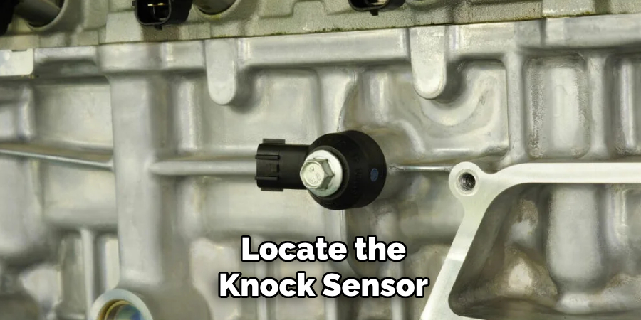
Source: qaqooking.wiki
Use the correct PID definition
Read the scan tool definition before interpreting a value. The same general term can represent different calculations on different vehicles.
Save fault information
Record diagnostic trouble codes and freeze-frame data before clearing anything.
Record operating conditions
Note coolant temperature, RPM, load, vehicle speed, gear, throttle position, and fuel being used when the knock-related change occurs.
Use a controlled test
Compare similar operating conditions instead of comparing unrelated idle, cruise, and acceleration events.
Which PIDs Should You Log?
For a useful knock-data log, start with the knock-related PID supported by the vehicle and then add the operating data needed to interpret it. A practical group can include engine RPM, calculated load or another reliable load parameter, ignition timing or spark advance, coolant temperature, intake air temperature, short- and long-term fuel trims, throttle position, and misfire information when available.
If the diagnostic tool provides cylinder-specific or bank-specific knock information, record that as well. A repeatable event isolated to one cylinder or one bank can provide a different diagnostic direction from a similar change occurring across the entire engine.
Core knock data
Use knock retard, knock correction, knock activity, knock counts, or the manufacturer-specific knock parameter available for the vehicle.
Timing data
Compare the knock-related value with commanded or reported ignition timing when the tool provides it.
Engine conditions
Log RPM, load, throttle position, temperatures, and other conditions that identify when the event happens.
Supporting data
Fuel trims and misfire data can help identify other engine problems that may accompany or resemble a knock-related issue.
How to Read Knock Sensor Data Step by Step
The most useful approach is to look for repeatable relationships between knock-related data and engine operating conditions. Do not diagnose the sensor from a single number on the screen.
The following process works as a general framework. Vehicle-specific service information takes priority whenever it gives a different test procedure or defines a PID differently.
Source: pinterest.com
1. Scan for trouble codes
Check the powertrain control module for stored, pending, and relevant history codes. Record the codes and freeze-frame information before clearing them.
2. Identify the knock parameters
Find the exact definitions for knock sensor voltage, knock activity, knock retard, knock correction, or other knock-related PIDs available for the vehicle.
3. Establish a baseline
Observe the engine at warm idle and during stable operating conditions. Record the values instead of relying on memory.
4. Watch the change under load
During a safe and appropriate test, observe whether knock-related corrections appear at a repeatable RPM, load, temperature, or throttle condition.
5. Compare timing
Look at ignition timing alongside knock retard. A timing reduction tells you that the control system changed ignition timing; it does not independently establish the cause.
6. Compare supporting PIDs
Check fuel trims, temperatures, load, RPM, and misfire data for changes that occur at the same time as the knock-related event.
7. Repeat the condition
A repeatable pattern is generally more useful diagnostically than one isolated spike. Reproduce the same operating condition when it can be done safely.
8. Verify with service information
Use the vehicle manufacturer’s test procedure to determine whether the observed behavior points toward the sensor, wiring, engine condition, calibration, or another system.
Step 1: Look at Knock Retard in Context
If your vehicle reports knock retard, first determine whether the value changes from its baseline and under what conditions. A temporary correction during a specific high-load event should not be interpreted the same way as persistent correction during normal operation.
The direction and display format also matter. Some scan tools show the amount of timing removed as a positive value, while others may display timing corrections with a different sign convention. Always use the definition supplied by the vehicle or diagnostic software.
Brief event
A short correction that occurs during a repeatable operating condition should be investigated in relation to that condition.
Persistent correction
Repeated knock-related correction across similar conditions deserves further diagnosis rather than being dismissed as a normal single event.
No correction
A zero or unchanged knock-retard value does not prove that the sensor or entire knock-control system is healthy. Other data and circuit tests may still be required.
Step 2: Compare Knock Data With Ignition Timing
Ignition timing tells you when the control module is commanding the spark event relative to the engine cycle, while knock retard describes a correction or removal of timing in systems that expose that parameter. Looking at both can show how the control system reacts when knock-related activity is detected.
For example, if ignition timing changes at the same moment that a knock-retard value rises, the two signals are related in the control strategy. That observation still does not identify the root cause. Fuel quality, temperature, engine load, deposits, mixture problems, mechanical noise, and other conditions can affect knock behavior.
Step 3: Compare the Event With RPM and Load
RPM and engine load provide essential context. If knock-related corrections repeatedly appear only in a particular load and RPM range, that pattern is more informative than a random spike recorded while the engine is changing conditions.
Record whether the event happens during acceleration, steady cruise, a gear change, uphill operation, or another specific condition. A pattern that follows load rather than engine speed can point the investigation in a different direction from an event that follows a narrow RPM band.
How to Interpret Knock Sensor Voltage
Knock sensor voltage is one of the easiest values to misinterpret. A voltage shown by a scan tool is not automatically a universal measurement of knock severity. Sensor construction, signal conditioning, control-module strategy, PID definitions, and the diagnostic tool all affect what the displayed value means.
Some knock sensors generate an electrical signal in response to engine vibration, and the control module processes that signal to determine whether it matches characteristics associated with knock. Other systems may display a processed value rather than the raw electrical waveform. This is why a voltage number from one vehicle should not be applied to another vehicle.
If a service manual provides a specified voltage test, follow that procedure exactly. It may require a particular engine speed, temperature, connector state, measurement location, or test instrument. A generic voltage range found online should not replace the manufacturer’s procedure.
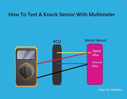
Source: safetyfic.com
Do not use one universal voltage range
Knock sensor electrical characteristics and scan-tool PIDs vary by vehicle and sensor system.
Understand the measurement point
A scan tool value, a multimeter reading, and an oscilloscope waveform are different measurements and should not be treated as identical.
Check the service manual
Use the exact voltage, resistance, waveform, connector, and operating-condition specifications for the vehicle being tested.
Look for behavior as well as magnitude
A change that consistently follows a controlled operating condition can be more useful than an isolated displayed number.
Scan Tool Versus Oscilloscope Data
A scan tool displays information that the control module makes available through its diagnostic interface. An oscilloscope can show an electrical waveform directly at the sensor or circuit under the correct test conditions. These tools answer different questions.
If the scan tool shows an unusual knock-related value, an oscilloscope or electrical test may be needed to determine whether the sensor and wiring are producing an appropriate signal. The correct test depends on the vehicle’s diagnostic procedure.
How to Tell Real Knock From a False Knock Pattern
Knock-related data does not automatically prove that damaging combustion knock is occurring. The control system is designed to detect vibration patterns, and unwanted mechanical noise can complicate interpretation. The goal is to determine whether the data represents genuine combustion-related activity, an electrical problem, mechanical noise, or another control-system condition.
A useful first step is to look for repeatability. If the same knock-related correction occurs at the same RPM and load, record the conditions and compare them with engine temperature, fuel, ignition timing, and other available data. If the event changes after a known condition changes, that relationship can help guide further testing.
Do not deliberately create severe engine knock to test a sensor. A controlled diagnostic procedure from the manufacturer should be followed when a functional test is required. Some systems can be tested with specified signal-generation or mechanical procedures, but the correct method is vehicle-specific.
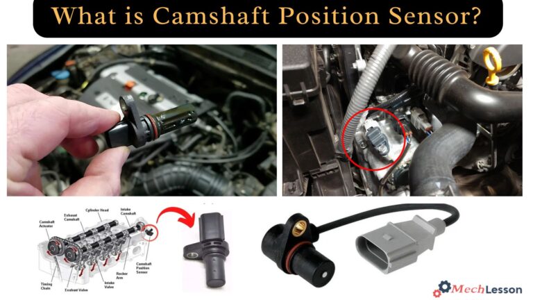
Source: mechlesson.com
Check whether the event repeats
Repeated behavior under the same conditions is more useful than an isolated spike.
Check for mechanical noise
Engine and drivetrain noises can complicate knock detection. Investigate abnormal mechanical noises rather than assuming the sensor is at fault.
Check fuel and temperature conditions
Fuel characteristics, intake temperature, coolant temperature, and engine load can affect knock tendency and should be recorded.
Check for electrical faults
Wiring, connectors, sensor faults, and control-module issues can alter knock-related readings or trigger diagnostic trouble codes.
Why a Knock Retard Spike Is Not a Diagnosis
A knock-retard spike tells you that the control system applied a timing correction or reported knock-related activity according to its strategy. It does not identify the underlying cause by itself.
For diagnosis, combine the knock event with the conditions surrounding it. A complete investigation may include fuel quality, air-fuel control, intake and coolant temperatures, ignition components, engine deposits, mechanical condition, sensor wiring, and manufacturer-specific control-system tests.
Common Knock Sensor Data Mistakes
Many incorrect diagnoses happen because a single live-data value is treated as a universal pass-or-fail measurement. Knock control is more complicated than that. The displayed number must be interpreted using the vehicle’s definitions and operating conditions.
Another common mistake is replacing the knock sensor immediately after seeing knock retard. The control module may be responding correctly to an engine condition, or the knock-related reading may be affected by another fault. Parts replacement should follow testing rather than replace it.
Source: storage.googleapis.com
Mistake: treating zero as proof of a good sensor
A zero knock-retard value only describes that particular displayed parameter and operating condition. It does not prove that every part of the knock-control system is functioning correctly.
Mistake: treating any timing correction as engine damage
Timing correction indicates control-system activity. Additional evidence is needed to determine why the correction occurred.
Mistake: using another vehicle’s voltage specification
Sensor systems and diagnostic strategies differ, so another engine’s voltage range may be irrelevant.
Mistake: ignoring fuel trims and temperature
Supporting data can reveal operating conditions that help explain a repeatable knock-related event.
Mistake: logging too little information
A knock value without RPM, load, timing, and temperature can make a useful event difficult to interpret.
Mistake: replacing parts before confirming the circuit
A sensor code or unusual PID should be followed by the manufacturer’s electrical and functional tests before parts are replaced.
When You Should Stop Relying on Generic Live Data
Move to manufacturer-specific service information when you encounter a knock sensor circuit code, an unexplained persistent correction, cylinder-specific data, unusual sensor voltage, or a value that conflicts with normal engine behavior.
A factory service procedure may specify connector tests, wiring checks, resistance or voltage measurements, waveform checks, sensor installation requirements, or control-module tests. Those instructions are more appropriate than a generic online normal-value chart.
Use vehicle-specific specifications
Verify the exact engine and control-module configuration before applying a diagnostic specification.
Check the circuit
Test the wiring, grounds, connectors, and sensor according to the manufacturer’s procedure.
Escalate persistent problems
If the vehicle continues to show abnormal knock-related behavior or has severe engine symptoms, professional diagnosis may be appropriate.
A Practical Example of Reading Knock Data
Consider a hypothetical gasoline engine where the scan tool shows a small knock-retard correction during moderate acceleration. The value appears only after the engine reaches a particular combination of RPM and load, while the engine is fully warmed up.
Do not immediately conclude that the knock sensor is defective. First compare the event with ignition timing, engine load, intake air temperature, coolant temperature, fuel trims, and misfire information. Repeat the same operating condition safely and see whether the pattern returns.
If the correction consistently follows the same condition, the next diagnostic step is to identify what can cause that operating-specific response. The investigation may include fuel quality, combustion conditions, temperature, ignition components, deposits, mechanical noise, or a sensor and circuit problem.
This example demonstrates why how to read knock sensor data is mainly a process of comparison. The useful question is not simply whether a number is high or low. The better question is what changed, when it changed, and whether the change can be reproduced and explained.
Source: apogeeweb.net
Baseline
Record knock-related data and supporting PIDs under stable operating conditions.
Event
Identify the exact RPM, load, temperature, and timing conditions when the knock-related value changes.
Repeat
Determine whether the same pattern occurs again under comparable conditions.
Investigate
Use the pattern and vehicle-specific service information to select the next diagnostic test.
What a Useful Data Log Looks Like
A useful log makes the knock event easy to match with engine conditions. Instead of recording only the knock PID, capture enough related data to identify the operating state at the moment the value changes.
For example, a log might show that a knock-retard event begins as load increases, occurs at a repeatable engine-speed range, and coincides with a change in ignition timing. That is more informative than a screenshot showing a single knock value with no context.
What to Do If Knock Sensor Data Looks Abnormal
If knock-related data looks abnormal, avoid jumping directly to sensor replacement. Start by documenting the exact parameter, its definition, the conditions under which it changes, and any related diagnostic trouble codes.
Next, compare the data with the manufacturer’s expected behavior. If the scan tool exposes a manufacturer-specific PID, its service documentation may provide a much more useful interpretation than generic OBD-II charts. Generic OBD-II information does not cover every enhanced knock-control parameter.
If the data points toward a circuit problem, perform the specified electrical tests. If the data points toward repeated knock control without an electrical fault, investigate the engine operating conditions that could contribute to the event. Severe knocking, unusual engine noise, loss of power, overheating, or other significant symptoms should be addressed promptly rather than repeatedly testing the vehicle under stressful conditions.
The goal is to identify the cause of the knock-control response, not simply to make the displayed knock number disappear.
Source: pinterest.com
Record the evidence
Save codes, freeze-frame information, live-data logs, and the exact operating conditions.
Confirm the PID definition
Make sure you know whether the displayed value is a raw signal, calculated value, correction, status, or counter.
Check related systems
Review ignition, fueling, temperature, load, misfire, and mechanical information as appropriate.
Follow the factory test
Use the vehicle-specific diagnostic procedure before condemning the knock sensor or control module.
Frequently Asked Questions
Q
What should knock sensor data look like at idle?
There is no single universal knock sensor value that applies to every vehicle at idle. The displayed value depends on the sensor design, control-module strategy, scan-tool PID, engine condition, and manufacturer specifications.
Use the vehicle-specific data definition and compare the reading with a known-good operating condition rather than relying on a generic online range.
Q
What does knock retard mean on a scan tool?
Knock retard generally represents ignition timing that the control module has removed or corrected as part of its knock-control strategy. The exact definition and display format vary between vehicles.
Knock retard is a control response, so it should not automatically be treated as a direct measurement of actual combustion knock.
Q
Can I diagnose a bad knock sensor from live data alone?
Usually, live data is evidence rather than a complete diagnosis. An unusual knock-related value can indicate a sensor, wiring, control strategy, engine operating condition, or mechanical-noise issue.
When the data is abnormal, use the manufacturer’s diagnostic procedure to confirm the sensor circuit and related systems before replacing parts.
Q
Is higher knock sensor voltage always bad?
No. A higher displayed voltage cannot be judged without knowing what the vehicle’s PID represents and what operating conditions existed when it was recorded. Knock sensors respond to engine vibration, and the control module processes that signal according to its calibration.
Use the exact service specification for the vehicle rather than applying a universal voltage threshold.
Q
Why does knock retard appear when I cannot hear engine knock?
The knock-control system evaluates vibration signals electronically, and the event may not be audible from the driver’s seat. Mechanical noise and other vibration sources can also affect the detection strategy.
If knock retard appears repeatedly without an obvious cause, compare the event with RPM, load, temperature, timing, misfire information, and the manufacturer’s diagnostic tests.
Q
Does zero knock retard mean the engine has no knock problem?
Not necessarily. Zero knock retard means that the displayed correction was zero under the observed conditions. It does not prove that the sensor, wiring, calibration, and complete knock-control system are fault-free.
If symptoms or trouble codes are present, continue with the appropriate diagnostic procedure instead of using zero as a universal health check.
✦ Wrapping Up
Conclusion
The most reliable way to read knock sensor data is to treat it as part of a larger diagnostic picture. Identify exactly what the scan tool PID means, establish a baseline, observe the data under controlled conditions, and compare knock-related changes with RPM, load, ignition timing, temperature, fuel trims, and misfire information.
Remember that knock retard is usually a control response rather than a direct measurement of combustion knock, and raw knock sensor voltage is not governed by one universal range. When a pattern looks abnormal, use vehicle-specific service information to separate a sensor or wiring fault from an engine condition that is causing the control module to react.
💡 Key Takeaway
Save the vehicle’s trouble codes and freeze-frame data, log knock-related parameters with RPM and load, identify repeatable patterns, and confirm the diagnosis with the manufacturer’s service procedure before replacing a knock sensor.
Ethan Brooks is an automotive writer at Auto News 7, covering car news, vehicle maintenance, new model updates, recalls, and practical buying guides. He focuses on clear, useful information that helps drivers understand their vehicles and make better ownership decisions.
Learn how often to replace camshaft position sensor components, expected lifespan, warning signs, replacement costs, and when replacement is necessary.
Learn how to test a single wire knock sensor with a multimeter, check its wiring and ground path, interpret resistance readings, and avoid common testing mistakes.