You can test a crankshaft position sensor without a multimeter by checking OBD-II live RPM while cranking, inspecting the sensor and wiring, watching for related trouble codes, checking for spark or injector activity where appropriate, and using an oscilloscope or test equipment if available.
For drivers and DIY mechanics in the United States, the easiest starting point is usually the vehicle’s OBD-II system. U.S.-market light-duty cars and trucks from the mid-1990s onward commonly provide standardized diagnostic access, so even an inexpensive scan tool may show whether the engine control module is seeing crankshaft speed while the starter turns the engine. If the scan tool stays at 0 RPM during a crank-no-start condition, the crankshaft position sensor circuit becomes an important area to investigate. That result does not automatically prove the sensor itself has failed.
The safest way to learn how to test crankshaft position sensor without multimeter is to diagnose the complete system rather than relying on one symptom. A damaged connector, broken wire, weak battery, excessive sensor air gap, damaged reluctor wheel, loss of sensor power or ground, or another engine-management fault can imitate a failed crankshaft sensor. The steps below begin with checks that require little or no electrical test equipment and then explain when a more precise test is necessary.
Source: hitchesguide.com
How to Test Crankshaft Position Sensor Without Multimeter
Start with the vehicle assembled and avoid removing the crankshaft position sensor unless access or inspection requires it. The goal is first to determine whether the engine control module appears to receive crankshaft-speed information while the engine is turning.
You will get the most useful results from an OBD-II scan tool that can display live data. A code reader that only reads and clears diagnostic trouble codes can still help, but live RPM data is much more informative for this test. You may also need a flashlight, basic hand tools, the correct service information for your year, make, model, and engine, and an assistant to crank the engine.
Before testing, confirm that the battery is reasonably charged and that the starter turns the engine at a normal speed. Slow cranking can complicate diagnosis, particularly on inductive crankshaft sensors whose signal strength changes with rotational speed.
Source: hitchesguide.com
Step 1: Scan for trouble codes
Connect an OBD-II scanner and check stored and pending codes. Codes in the P0335 through P0339 family can direct attention toward the crankshaft position sensor circuit, but a code identifies a circuit or signal problem rather than automatically proving the sensor is defective.
Step 2: Open live engine RPM data
Select engine speed or RPM on the scanner with the ignition on and the engine off.
Step 3: Crank the engine
Have an assistant operate the starter while you watch the RPM value. Keep hands, clothing, tools, and test equipment away from belts, pulleys, fans, and other moving components.
Step 4: Interpret the RPM reading
If a realistic cranking RPM appears, the control module is receiving at least some engine-speed information. If RPM remains at 0 while the crankshaft is physically rotating, investigate the crankshaft position sensor circuit, wiring, sensor power or ground where applicable, reluctor wheel, sensor mounting, and air gap.
Step 5: Repeat the test during the failure
An intermittent sensor may work when the engine is cold and fail after warming up. If the vehicle stalls or refuses to restart hot, scan RPM during the actual hot no-start condition rather than assuming a cold test rules out the sensor.
What Does 0 RPM While Cranking Mean?
A steady 0 RPM reading while the starter is visibly turning the engine means the scan tool is not receiving an engine-speed value from the control module. Because the crankshaft position signal is commonly used to determine engine speed, this is strong evidence that the CKP signal path deserves attention.
It is not a sensor verdict. A disconnected connector, broken conductor, corroded terminal, missing supply voltage on an active sensor, poor ground, damaged trigger wheel, excessive sensor-to-wheel gap, or even a control-module or communication issue can prevent usable RPM data from appearing.
0 RPM plus a crankshaft circuit code
This combination strengthens the case for checking the CKP circuit immediately.
0 RPM with no code
Do not rule out the CKP circuit. Some failures may not set a code immediately.
Normal cranking RPM
This means at least some crankshaft-speed data is reaching the computer, although an intermittent or distorted signal may still require waveform testing.
Inspect the Crankshaft Sensor, Connector, and Wiring
A careful visual inspection can reveal faults that mimic an internally failed sensor and requires no multimeter. Turn the ignition off before touching the connector or harness, and consult vehicle-specific service information to locate the crankshaft position sensor.
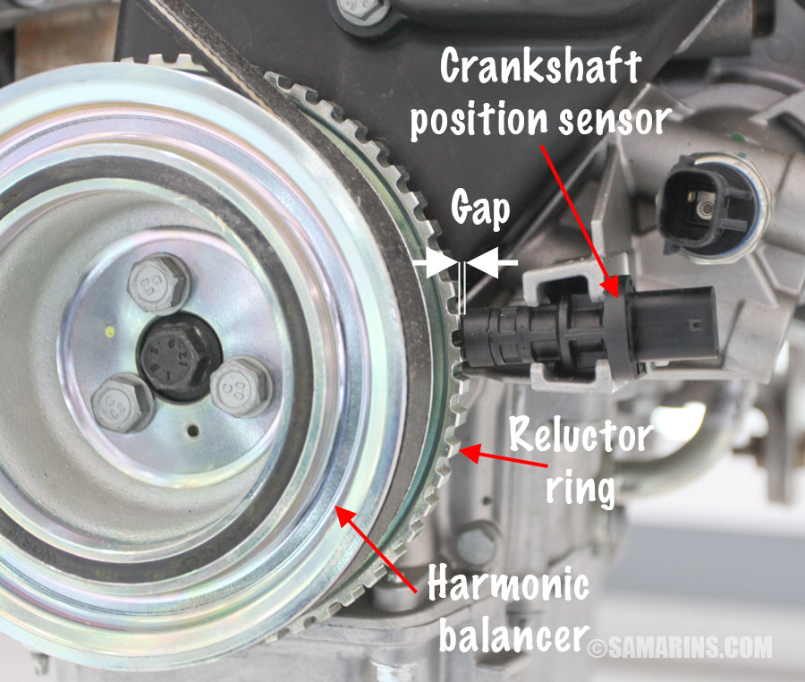
Depending on the engine, the CKP sensor may be positioned near the crankshaft pulley, harmonic balancer, timing cover, engine block, flywheel, flexplate, or transmission bell housing. Do not identify a sensor only by its shape because camshaft and crankshaft sensors can look similar.
Follow the wiring from the sensor as far as practical. Heat, engine movement, leaking oil, previous repairs, road debris, and contact with brackets can damage insulation or terminals. A connector that looks connected can still have a backed-out, spread, contaminated, or corroded terminal.
Source: brrlt.org
Check the connector lock
Make sure the plug is fully seated and the retaining tab is not broken.
Inspect terminals
Look for corrosion, moisture, bent pins, pushed-back terminals, looseness, or evidence of overheating.
Inspect the harness
Look for cuts, melted insulation, crushed sections, rodent damage, rubbing, or a wire stretched tightly near the engine.
Check sensor mounting
The sensor should normally be secure and positioned according to the manufacturer’s design. A loose sensor can alter the gap between the sensor and trigger wheel.
Look for contamination
Oil, dirt, metal debris, or damage around some magnetic sensor tips may interfere with normal operation. Clean only according to the service procedure.
Can You Perform a Wiggle Test?
A controlled harness wiggle test can help expose an intermittent connection. If the engine runs, monitor RPM and engine operation while gently moving accessible portions of the CKP harness and connector. Do not pull hard on wires or move anything near rotating components.
If the engine suddenly stalls, stumbles, or loses RPM data when one section of the harness is moved, inspect that area closely. The result indicates an intermittent circuit problem but does not automatically identify whether the fault is inside the wire, terminal, connector, or sensor.
Safety first
Keep your hands away from belts, cooling fans, exhaust components, and other moving or hot parts.
Use Symptoms as Clues, Not as Proof
Crankshaft position sensor symptoms can help you decide what to test next, but symptoms alone cannot confirm a failed sensor. The crankshaft sensor supplies timing and speed information that the engine computer may use for ignition, fuel injection, misfire monitoring, and synchronization. Losing that information can therefore affect starting and engine operation in several ways.
Common complaints associated with a CKP signal problem include an engine that cranks but will not start, intermittent stalling, hard starting, extended cranking, rough running, misfires, poor acceleration, or a check engine light. The exact behavior depends on the vehicle’s control strategy and whether the signal is missing completely, intermittent, or merely distorted.
Many unrelated faults can create the same symptoms. A crank-no-start condition can also result from a weak battery, failed fuel pump, ignition-system problem, immobilizer issue, timing failure, loss of compression, blown fuse, defective relay, or another sensor or circuit fault.
Source: hitchesguide.com
Cranks normally but will not start
Check scan-tool RPM early in the diagnosis. A missing RPM signal provides a useful direction.
Starts cold but stalls when hot
Monitor live RPM when the failure actually occurs. Heat-related CKP or wiring failures can be intermittent.
Tachometer behaves abnormally
On some vehicles, a tachometer that stays at zero while cranking may support suspicion of a missing engine-speed signal, but scan data is more useful because dashboard behavior differs between models.
Check engine light is on
Read codes before disconnecting the battery or clearing memory. The stored information may help preserve evidence of an intermittent fault.
Can You Test the Sensor by Checking for Spark?
A spark check may provide supporting information on some gasoline vehicles because the control module may stop ignition triggering when it cannot determine crankshaft position. However, no spark does not prove that the crankshaft position sensor is bad.
Ignition coils, power supplies, fuses, grounds, security systems, wiring, control modules, camshaft synchronization, and other faults can also eliminate spark. Use a purpose-built spark tester and follow the vehicle manufacturer’s procedure rather than holding an ignition wire or coil near your body.
Useful result
No spark combined with 0 RPM while cranking gives you more reason to inspect the CKP system.
Important limitation
Spark alone cannot determine whether the sensor, wiring, trigger wheel, or another control-system component is responsible.
Can Injector Operation Help Diagnose a CKP Problem?
Injector activity can also provide a supporting clue because some control systems require valid engine-position information before commanding normal fuel injection. A noid light connected according to the service procedure can show whether injector pulse is present on applications where that test is appropriate.
Again, missing injector pulse is not a crankshaft sensor test by itself. Power-supply faults, immobilizer operation, wiring problems, control-module faults, or other conditions can suppress injector operation.
Use multiple clues together
0 scan-tool RPM, no spark, and no injector command during cranking may point strongly toward a missing engine-position reference, but the complete circuit still needs diagnosis.
Understand the Sensor Type Before Trying Any Direct Test
Crankshaft position sensors do not all operate the same way. This is one reason improvised universal tests are unreliable. The two broad categories commonly encountered are passive inductive, sometimes called variable-reluctance sensors, and active electronic sensors such as Hall-effect designs.
An inductive sensor generates an alternating signal as the teeth of a reluctor wheel pass the magnetic pickup. An active sensor requires a power supply and ground and sends an electronically switched signal to the control module. Wire count can provide a clue, but it is not a dependable identification method by itself.
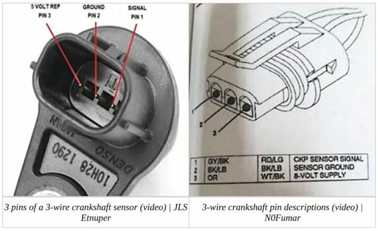
Some passive sensors have two conductors, while a shielded design can include another connection. Active sensors commonly have power, ground, and signal circuits, but the exact terminal layout, supply voltage, and signal design must be confirmed from vehicle-specific service information.
Source: thecarhow.com
Do not assume two wires always means one sensor type
Connector design varies by manufacturer and application.
Do not assume every active sensor uses the same voltage
The correct power supply and signal specification must come from the service information for the exact vehicle.
Avoid random jumper-wire tests
Shorting a signal, reference, or power circuit can damage wiring, a sensor, or a control module.
Avoid resistance testing an unidentified active sensor
If electrical testing becomes necessary, identify the sensor design and use the manufacturer’s procedure.
Why the Popular Magnet Test Is Not Conclusive
Some DIY guides suggest placing metal near a removed sensor and judging it by magnetic attraction. This is not a dependable pass-or-fail test. Even if a magnetic sensor attracts steel, that does not show whether its winding, electronics, output signal, wiring, mounting gap, or trigger wheel works correctly during cranking.
The reverse is also true: weak or absent attraction does not automatically prove that every sensor design is defective. Use the magnet check, if applicable at all, only as a basic observation rather than a diagnosis.
Better alternative
Use live RPM, trouble codes, visual inspection, and waveform testing when necessary.
Do Not Use the Tongue or Shock Test
Do not put sensor terminals, wires, test leads, or electrical components in your mouth. Online demonstrations sometimes suggest touching sensor pins to the tongue while striking or moving the sensor to feel a small electrical sensation. That is not an acceptable automotive diagnostic method.
It cannot establish waveform quality, sensor timing, circuit integrity, or correct operation under real engine conditions, and deliberately placing electrical components against the body is unnecessary. Use proper test equipment instead.
Safe rule
Never use your body as an electrical test instrument.
How to Interpret Your Results and Decide What to Do Next
The most useful no-multimeter diagnosis combines scan data, physical inspection, symptoms, and vehicle-specific information. Avoid replacing the crankshaft position sensor based on a single clue.
If live data shows a believable RPM value every time the engine cranks, the control module is receiving some form of crankshaft-speed information. That makes a completely dead CKP signal less likely, although it does not rule out signal distortion, incorrect timing, intermittent dropouts, a damaged reluctor pattern, or a problem that appears only when hot.
If the engine cranks normally but scan data remains at 0 RPM, inspect the CKP connector and harness carefully and check for relevant codes. If no obvious fault appears, the next reliable step is usually circuit testing or waveform analysis according to the service manual.
An automotive oscilloscope is especially valuable because it shows the signal over time rather than reducing it to one averaged electrical reading. A technician can use the waveform to identify dropouts, irregular pulse spacing, missing or damaged reluctor teeth, weak inductive output, incorrect high and low states, noise, or intermittent failure.
Source: hitchesguide.com
Normal RPM and engine starts
A completely failed CKP sensor is unlikely at that moment. Investigate the actual symptom and any stored codes rather than replacing the sensor automatically.
Normal RPM but intermittent stalling
Monitor RPM when the stall occurs. Heat, vibration, wiring movement, or waveform distortion may create an intermittent problem.
0 RPM with obvious wiring damage
Repair the circuit correctly before judging the sensor.
0 RPM with connector and wiring appearing normal
Use vehicle-specific electrical checks or an oscilloscope to determine whether the sensor is producing a usable signal.
CKP-related code with normal live RPM
Read the exact code definition and freeze-frame data. Range, performance, correlation, intermittent, high, and low-signal faults require different diagnostic directions.
New sensor does not fix the problem
Recheck wiring, terminals, sensor installation, air gap where applicable, reluctor condition, battery and cranking performance, and manufacturer-required setup or relearn procedures.
What Trouble Codes Can Be Related to a Crankshaft Position Sensor?
Common generic crankshaft position sensor circuit codes include P0335, P0336, P0337, P0338, and P0339. Their exact wording may describe a circuit malfunction, range or performance problem, low input, high input, or intermittent condition.
Correlation codes can also matter when the control module detects a disagreement between crankshaft and camshaft timing. These codes can result from sensor or wiring faults, but they may also be associated with mechanical timing, trigger-wheel, installation, or synchronization problems. Always diagnose the meaning of the exact code instead of treating every CKP-related code as an instruction to replace the sensor.
P0335
Generally relates to a crankshaft position sensor A circuit fault.
P0336
Generally relates to crankshaft position sensor range or performance.
P0337 and P0338
Generally indicate low-input or high-input circuit conditions.
P0339
Generally indicates an intermittent crankshaft position sensor circuit condition.
When Should You Stop DIY Testing?
Professional diagnosis is appropriate when the sensor is difficult to access, wiring disappears into a complex harness, the engine has mechanical timing concerns, scan data conflicts with symptoms, or the next step requires powered-circuit testing at control-module terminals.
A technician with an oscilloscope, wiring diagrams, breakout leads, and vehicle-specific service information can compare the actual crankshaft waveform with the camshaft signal and determine whether the problem originates in the sensor, trigger wheel, wiring, power supply, grounding, mechanical timing, or control system.
This can be more economical than repeatedly replacing sensors because symptoms overlap with many other no-start and stalling faults.
Seek professional help
Do so if testing requires working close to moving engine components, accessing the starter or flywheel area, piercing or modifying wiring, or making control-module measurements you are not trained to perform.
Frequently Asked Questions About How to Test Crankshaft Position Sensor Without Multimeter
Q
Can you really test a crankshaft position sensor without a multimeter?
Yes, you can perform useful diagnostic checks without a multimeter. The best starting method is usually to watch engine RPM with an OBD-II scan tool while the engine is cranking, then inspect the sensor connector, wiring, mounting, and related trouble codes.
These checks can tell you whether the crankshaft position signal is missing or suspicious, but they may not prove that the sensor itself is defective. A conclusive diagnosis may still require electrical circuit testing or an oscilloscope.
Q
Should RPM show on a scanner while cranking?
On vehicles that provide engine-speed live data, you should normally see a nonzero RPM value while the starter is rotating the engine. The exact cranking speed varies with the engine, battery condition, temperature, starter performance, and vehicle design.
Do not diagnose the sensor from a universal RPM number. The key observation is whether the control module recognizes plausible engine rotation. A steady 0 RPM reading during a confirmed crank-no-start condition deserves further CKP circuit investigation.
Q
Will a bad crankshaft position sensor always set a code?
No. Some failures may set a crankshaft position sensor code quickly, while intermittent or unusual failures may not immediately trigger a diagnostic trouble code. Code-setting logic also differs by vehicle.
For that reason, combine stored and pending codes with live RPM, symptoms, wiring inspection, and testing during the actual failure.
Q
Can a bad crankshaft position sensor cause a crank-no-start?
Yes. If the engine computer cannot determine crankshaft position or speed, some vehicles may not provide the ignition or fuel-injection commands needed for the engine to start.
However, a crank-no-start has many other possible causes, including fuel-delivery faults, ignition failures, security-system problems, battery or cranking issues, mechanical timing faults, compression problems, wiring faults, or other sensor failures.
Q
Can I unplug the crankshaft sensor to see if the engine runs differently?
Unplugging the sensor is not a reliable universal test. Many engines will not start or run normally without a usable CKP signal, and the test may simply create additional trouble codes without revealing whether the original problem was the sensor, wiring, or another component.
Use live scan data and inspection first. Disconnect connectors only with the ignition off and when the service procedure calls for it.
Q
Can a camshaft sensor be mistaken for a bad crankshaft sensor?
Yes. Camshaft and crankshaft position signals are related because the control module may compare them for engine synchronization. Wiring problems, mechanical timing errors, damaged trigger wheels, or a faulty camshaft sensor can sometimes create symptoms or correlation codes that complicate CKP diagnosis.
Read all diagnostic codes and identify the exact sensor and circuit before replacing anything.
Q
Does a new crankshaft position sensor need a relearn?
Some vehicles require a crankshaft position variation relearn or another manufacturer-specific procedure after sensor replacement or certain engine, transmission, reluctor, or control-module repairs. Other vehicles do not require the same procedure.
Check service information for the exact U.S.-market year, make, model, engine, and powertrain. A relearn requirement is a post-repair consideration and should not be used as proof that the original sensor was faulty.
✦ Wrapping Up
Conclusion
The practical answer to how to test crankshaft position sensor without multimeter is to start with OBD-II live data. Watch engine RPM while cranking, read stored and pending trouble codes, and inspect the CKP sensor connector, harness, mounting, and surrounding area. A normal RPM value means the computer is receiving at least some crankshaft-speed information, while a steady 0 RPM during confirmed engine cranking makes the CKP signal path an important diagnostic target.
Do not replace the sensor based only on a no-start, stalling complaint, a single code, a dashboard tachometer, or an improvised magnet test. Wiring damage, poor connections, active-sensor power or ground problems, a weak battery, slow cranking, incorrect sensor gap, a damaged reluctor wheel, mechanical timing faults, and other engine-management problems can produce similar symptoms.
If the scan-tool and visual checks leave the answer uncertain, move to manufacturer-specified circuit testing or an oscilloscope waveform test. That approach verifies what the sensor and control module are actually seeing and helps avoid replacing a good part.
💡 Key Takeaway
Connect an OBD-II scanner, monitor engine RPM while cranking, inspect the CKP connector and harness if RPM stays at 0, and use proper electrical or waveform testing before replacing the sensor when the cause remains uncertain.
Ethan Brooks is an automotive writer at Auto News 7, covering car news, vehicle maintenance, new model updates, recalls, and practical buying guides. He focuses on clear, useful information that helps drivers understand their vehicles and make better ownership decisions.