Wire a crankshaft position sensor according to the vehicle service diagram, because wire functions and connector pinouts vary by engine.
If you are working on a vehicle in the United States, the safest way to wire a crankshaft position sensor is to identify the exact vehicle, engine, sensor type, and connector pinout before joining any wires. A crankshaft position sensor, often called a CKP sensor, supplies the engine control module with information about crankshaft position and speed. The computer uses that information for functions such as ignition and fuel control.
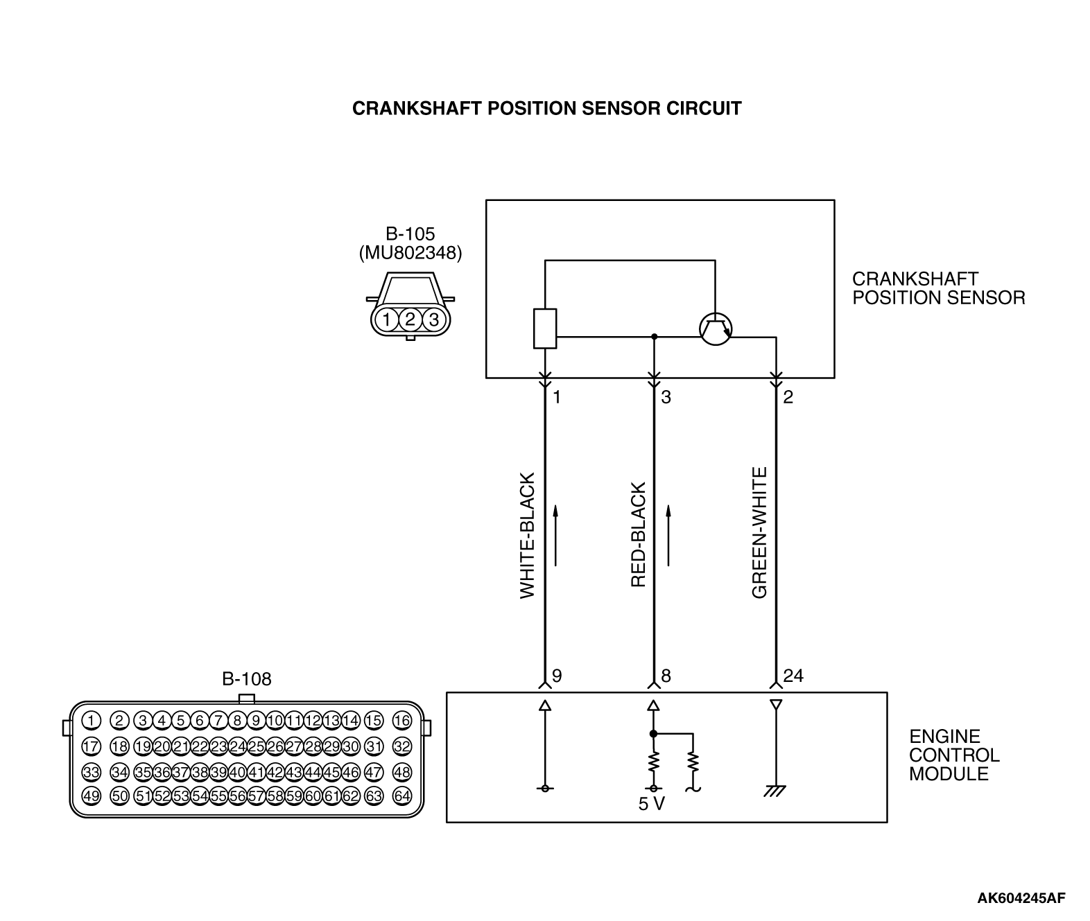
There is no universal crankshaft sensor wiring order. Some sensors are inductive and commonly use two wires, while many Hall-effect sensors use three wires for power, ground, and signal. Other designs use different circuits, including differential or current-based arrangements. Matching wires by color alone can therefore create a no-start condition or damage an electronic circuit. The correct wiring diagram and connector pin numbers should always take priority.
Source: mitsubishitechinfo.com
What Does a Crankshaft Position Sensor Do?
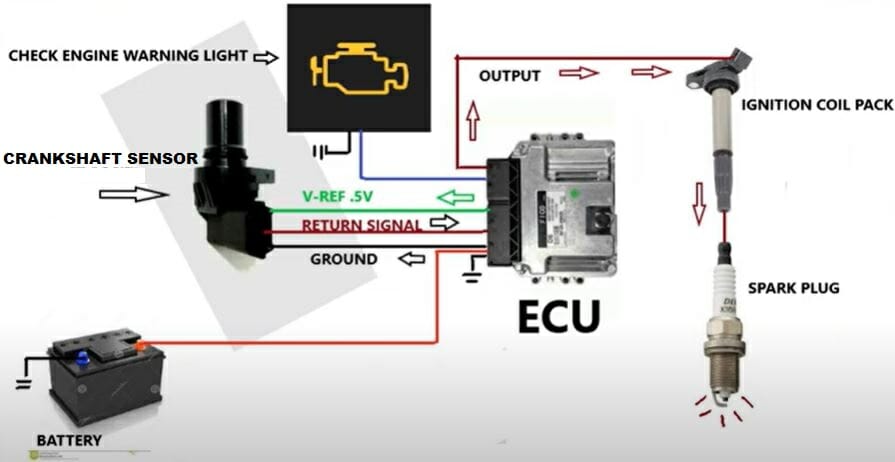
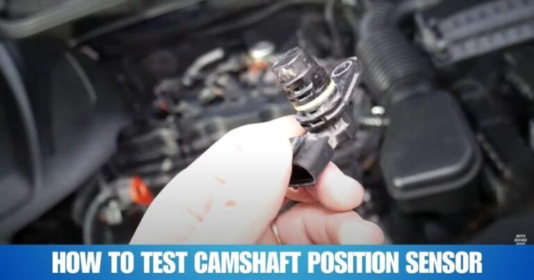
A crankshaft position sensor detects the position and rotational speed of the crankshaft. The sensor reads a toothed, notched, or otherwise patterned target wheel as it rotates. The engine control module uses the resulting signal to determine engine speed and crankshaft position.
The sensor is part of the engine management system, so a wiring fault can cause much more than a warning light. Depending on the vehicle, a missing or unreliable CKP signal can result in hard starting, stalling, loss of spark or injector control, or an engine that cranks without starting.
Crankshaft sensors are broadly available in inductive and Hall-effect designs. The electrical behavior is different between these designs, which is why the correct wiring method depends on the exact application.
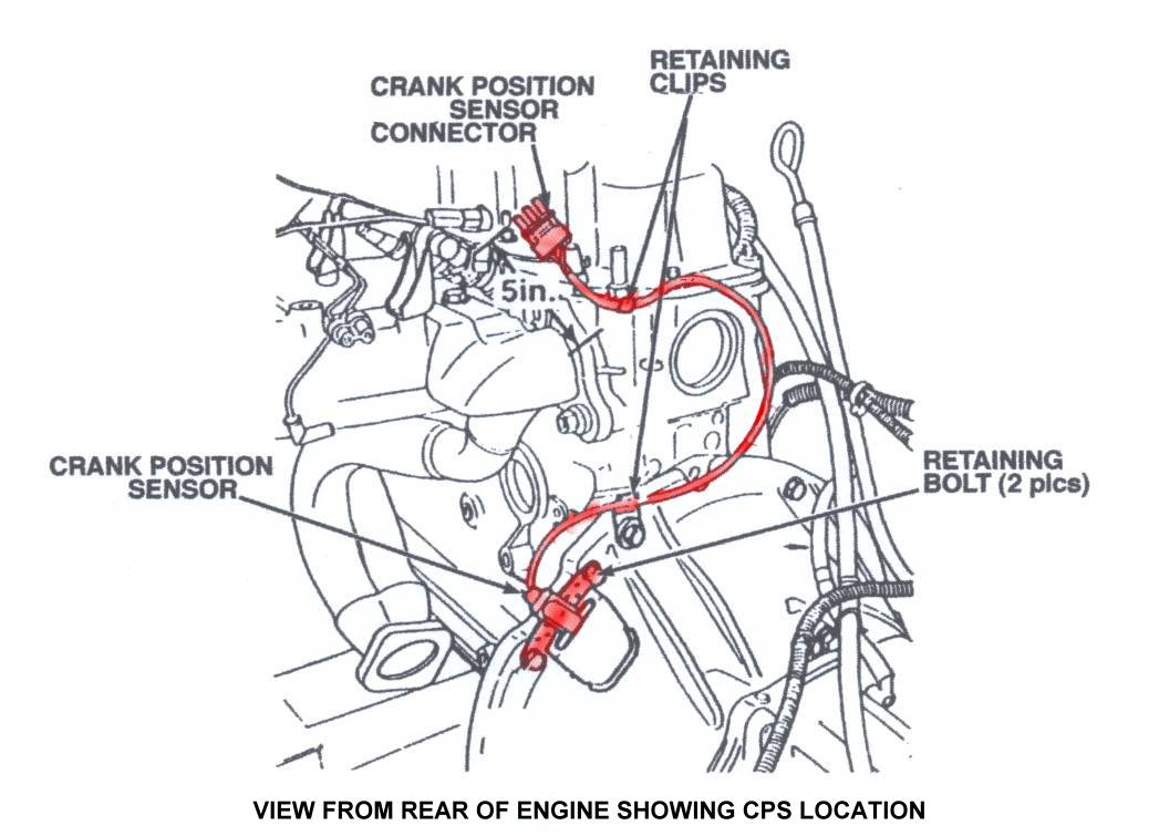
Source: lunghd.com
Inductive sensor
A common inductive CKP sensor uses two signal wires and generates an alternating electrical signal as the target wheel passes the sensor.
Hall-effect sensor
A common Hall-effect CKP sensor uses power, ground, and signal circuits and requires an electrical supply to operate.
Target wheel
The rotating crankshaft target provides the changing magnetic or electromagnetic condition that the sensor detects.
Before You Wire a Crankshaft Position Sensor
Before cutting or joining any wire, confirm the vehicle identification and obtain the wiring diagram for the exact engine. Use the vehicle identification number, model year, engine size, and engine code when available. A sensor connector that looks similar can have a different pinout on another engine or model year.
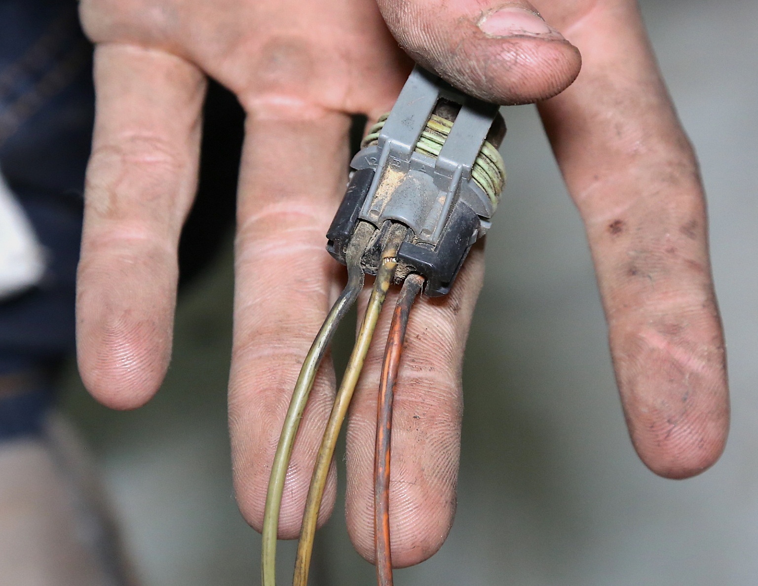
Inspect the original connector before assuming the sensor itself needs to be rewired. Look for broken locking tabs, pushed-back terminals, corrosion, moisture, damaged insulation, stretched wires, and previous repairs. A loose terminal can interrupt the CKP signal even when the sensor is new.
Gather a digital multimeter, the correct wiring diagram, appropriate wire repair materials, electrical connector tools, and any required scan or oscilloscope equipment. If access requires lifting the vehicle, use the manufacturer’s specified lifting points and appropriate support equipment.
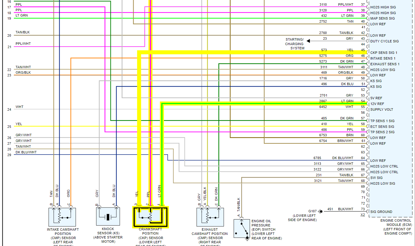
Source: nissankaengine.com
Vehicle information
Record the model year, make, model, engine, and engine code so the wiring diagram matches the vehicle.
Connector information
Identify connector cavity numbers rather than relying only on wire colors.
Sensor type
Determine whether the CKP sensor is inductive, Hall-effect, or another design before testing or connecting the circuit.
Repair materials
Use automotive-grade terminals, wire, seals, and repair methods suitable for the engine compartment.
Why the Vehicle-Specific Wiring Diagram Matters
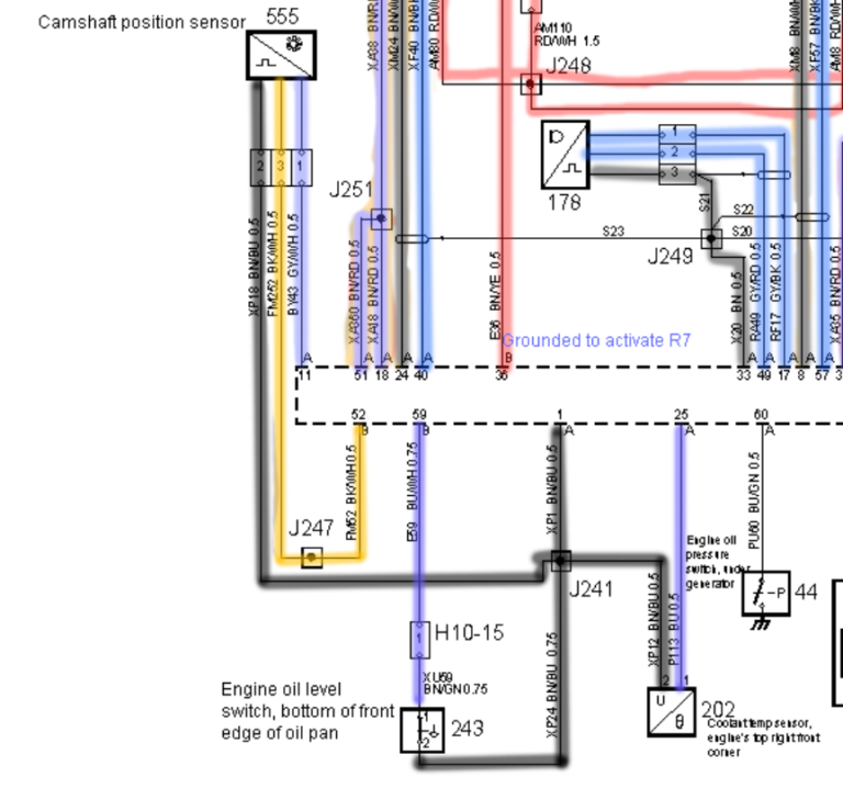
A generic diagram can explain how a sensor works, but it should not replace the manufacturer’s wiring diagram. Pin assignments, reference voltages, signal circuits, shielding, connector layouts, and ground arrangements can vary between engines.
The diagram should tell you which connector cavity belongs to each circuit and where the circuit travels. That information lets you test the wiring without guessing.
Power circuit
Some active sensors receive a regulated supply from the engine control system.
Ground circuit
A Hall-effect sensor may use a dedicated sensor ground that should not automatically be treated as interchangeable with another ground.
Signal circuit
The signal wire carries the information used by the control module to determine crankshaft movement and position.
How to Wire a Crankshaft Position Sensor
The basic repair process is to identify the circuits, disconnect power as required, verify the old wiring, repair each circuit to the correct terminal, protect the repair, and test the finished circuit. Do not connect wires simply because their colors appear to match.
If the connector has been damaged but the vehicle harness is intact, a replacement connector or pigtail is often preferable to creating several unnecessary splices. Follow the terminal orientation and cavity numbering shown in the vehicle wiring information.
Source: autotoride.com
Step 1: Identify the connector
Locate the CKP sensor connector and determine the connector cavity numbers from the vehicle wiring diagram.
Step 2: Identify each circuit
Determine which wire is power, ground, signal, or the appropriate paired circuit for the sensor design.
Step 3: Disconnect electrical power
Turn the ignition off and disconnect the battery when the manufacturer’s procedure calls for it before repairing the harness.
Step 4: Inspect the harness
Follow the wiring away from the sensor and look for chafing, melted insulation, corrosion, stretched sections, previous splices, and broken conductors.
Step 5: Repair the correct wires
Connect each conductor to the correct terminal using an appropriate automotive repair method and maintain the original circuit arrangement.
Step 6: Protect the harness
Secure the harness away from rotating parts, exhaust heat, sharp edges, and locations where engine movement could pull on the connector.
Step 7: Reconnect and test
Reconnect the electrical system and perform the specified power, ground, continuity, and signal checks before starting the engine.
How to Wire a Common Three-Wire Hall-Effect Sensor
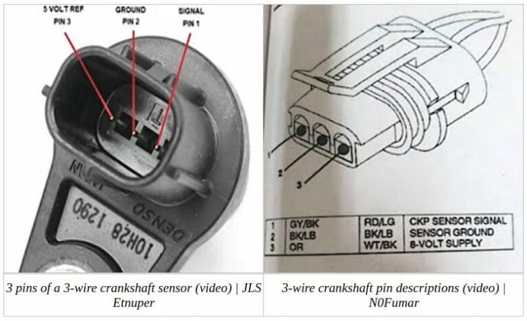
A common three-wire Hall-effect crankshaft sensor has three basic circuits: a power supply, a ground, and a signal output. The exact voltage and pin assignment must come from the vehicle’s wiring information. Do not assume that the middle pin, left pin, or a particular wire color always represents the same function.
With the connector identified, verify the supply and ground circuits using the manufacturer’s test procedure. Then verify the signal circuit. A functioning Hall-effect sensor should produce a changing output as the crankshaft target passes the sensing element, but the expected voltage pattern depends on the specific circuit design.
If power and ground are correct but the signal is absent, the fault may be the sensor, connector, target wheel, air gap, or signal wiring. Test those possibilities rather than immediately replacing the sensor.
Power
Connect the sensor power circuit to the correct supply identified by the vehicle wiring diagram.
Ground
Connect the sensor ground to its specified circuit and avoid substituting an unrelated ground.
Signal
Connect the sensor output to the specified engine control module signal circuit.
How to Wire a Common Two-Wire Inductive Sensor
A common two-wire inductive crankshaft sensor does not use the same power, ground, and signal arrangement as a three-wire Hall-effect sensor. The sensor generates an alternating electrical signal as the crankshaft target moves past it.
The two wires form the sensor circuit, and their polarity can matter for some engine management systems. Follow the manufacturer’s connector and polarity information instead of assuming that either wire can be connected to either terminal.
Because an inductive sensor produces a changing signal during cranking, testing the circuit with the correct AC measurement or an oscilloscope can be more informative than checking for a fixed supply voltage.
Do not add a power wire
A typical passive inductive sensor does not require the same external supply arrangement used by a powered Hall-effect sensor.
Check both conductors
Inspect the entire two-wire circuit for opens, shorts, poor terminals, and damage.
Check the signal while cranking
Use the vehicle’s specified test method to confirm that the sensor produces the expected changing signal.
How to Identify Crankshaft Sensor Wires
The most reliable way to identify CKP sensor wires is by connector cavity number and the vehicle wiring diagram. Wire color is useful as a secondary reference, but it should not be the only identification method.
Trace each circuit from the sensor connector toward the engine control module when the wiring information requires it. Compare the circuit path with the physical harness. This can reveal a previous repair where two wires were joined incorrectly or where a connector was repinned.
If a replacement pigtail is being installed, compare the terminal positions of the replacement connector with the original connector and the wiring diagram. Make one circuit change at a time and document the original arrangement before removing terminals.
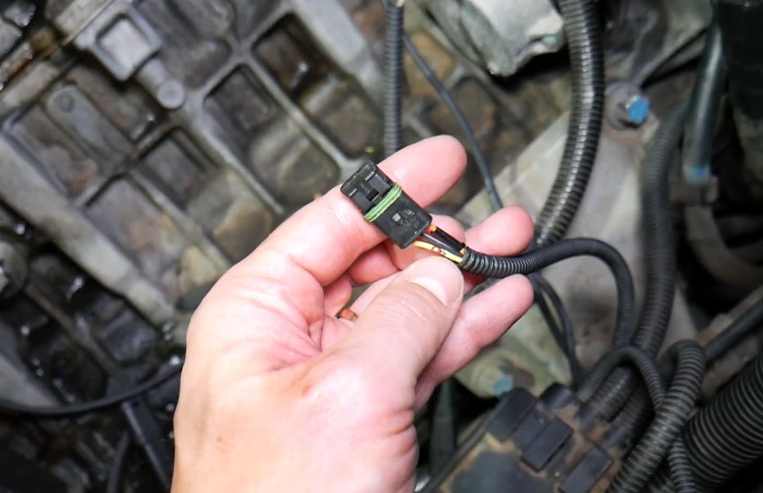
Source: i.ytimg.com
Use connector cavity numbers
Cavity numbers provide a more reliable reference than assuming a color has the same meaning on every vehicle.
Trace the circuit
Follow the wiring toward the engine control module and check for intermediate connectors or splices.
Check terminal condition
A visually intact wire can still have a loose, corroded, pushed-back, or damaged terminal.
Compare before repairing
Photograph and document the connector orientation and existing terminal positions before removing a damaged pigtail.
How to Test the Wiring After Repair
A wiring repair is not complete until the circuit has been tested. Start with visual inspection, then perform the electrical tests specified for the vehicle. The goal is to confirm that the correct circuit reaches the correct destination and that the sensor produces a usable signal during cranking or engine operation.
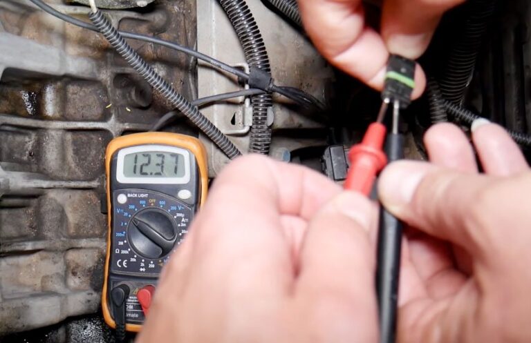
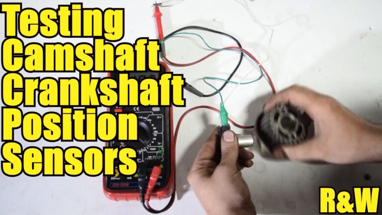
For a powered sensor, verify the specified supply and ground. For an inductive sensor, use the manufacturer’s method for checking the generated signal. An oscilloscope can provide more information about waveform quality and can help separate sensor faults from wiring faults.
Do not rely on an engine starting as the only proof of a good repair. A marginal connection can work temporarily and fail when vibration, heat, or engine movement changes the harness position.
Source: nissankaengine.com
Visual test
Check connector locking, terminal seating, insulation, routing, and protection from heat or abrasion.
Continuity test
When appropriate, verify that each repaired conductor has the expected electrical connection between its specified endpoints.
Short-circuit test
Check for unwanted continuity between the sensor circuits and other circuits according to the manufacturer’s diagnostic procedure.
Signal test
Confirm that the CKP signal changes correctly while the engine is cranked or running, using the specified meter or oscilloscope procedure.
Scan-tool test
Check for crankshaft-related diagnostic trouble codes and confirm that the scan data shows an engine-speed or synchronization signal when appropriate.
What a Failed Wiring Test Can Tell You
If a sensor has the correct supply and ground but the control module does not receive the expected signal, inspect the signal wire and its terminals before condemning the sensor. A broken conductor inside the insulation can create an intermittent fault that is difficult to find by sight alone.
If the signal is present at the sensor but absent at the engine control module, the wiring between those points becomes a primary suspect. A breakout connection or other non-damaging test method can help technicians compare the signal at different points in the circuit.
Signal at sensor but not at module
Inspect the signal circuit, connectors, intermediate splices, and terminals between the sensor and control module.
No power at an active sensor
Check the supply circuit, fuse or control circuit where applicable, connector condition, and wiring.
Poor ground
Check the sensor ground circuit and voltage drop using the vehicle-specific diagnostic procedure.
Signal changes when the harness moves
Suspect an intermittent connection, broken conductor, poor splice, or damaged terminal.
Common Crankshaft Position Sensor Wiring Problems
Most CKP wiring problems come from incorrect connections, damaged conductors, poor terminals, corrosion, or harness routing problems. A diagnostic code for a crankshaft position circuit does not automatically prove that the sensor itself has failed.
Start with the simplest useful inspection. Check the connector, wiring, sensor mounting, and target area before replacing parts. If the vehicle uses an adjustable or specified sensor-to-target clearance, follow the exact manufacturer procedure because an incorrect gap can affect signal quality.
Source: toolsweek.com
Wrong pin assignment
Connecting a wire to the wrong connector cavity can prevent the sensor from operating or create an electrical fault.
Broken conductor
A conductor can break inside its insulation after repeated vibration or previous harness damage.
Corroded connector
Moisture and corrosion can increase resistance or interrupt the low-level sensor signal.
Poor splice
An unsuitable or loose splice can create an intermittent connection, especially when the harness moves.
Harness routed too close to heat
Exhaust components and other high-temperature areas can damage insulation and eventually expose or short conductors.
Sensor or target problem
Correct wiring cannot compensate for a failed sensor, damaged target wheel, incorrect installation, or an incorrect sensor-to-target relationship.
Why a New Sensor May Still Not Fix the Problem
Replacing the CKP sensor without testing its circuit can leave the actual problem untouched. The engine control module may still be missing the signal because of a broken wire, poor ground, damaged connector, incorrect terminal position, or a target-wheel problem.
A useful diagnostic sequence is to verify the sensor type, inspect the connector, test the required circuits, confirm the sensor signal, and then compare the signal at the control module when necessary. This approach reduces unnecessary parts replacement.
Start with the circuit
Confirm that the electrical conditions required by the sensor are present before assuming the sensor has failed.
Check the mechanical installation
Verify that the sensor is installed correctly and is not contacting the rotating target.
Check the target
Inspect the reluctor or trigger wheel for damage, contamination, or another condition identified by the manufacturer.
Safety and Wiring Repair Boundaries
Work on a cool engine whenever possible and keep hands, tools, and wiring away from belts, pulleys, fans, and other moving parts. If the vehicle must be raised, use the manufacturer’s lifting points and properly rated support equipment.
Disconnecting the battery can affect vehicle settings and may not be appropriate for every diagnostic procedure. Follow the vehicle manufacturer’s service instructions, especially when testing circuits that require the control module or sensor to be powered.
Do not probe sealed connectors in a way that spreads terminals or damages weather seals. Use suitable back-probing or breakout equipment when the service procedure calls for live-circuit testing. If the wiring diagram is unavailable or the repair involves a complex engine management circuit, a qualified automotive technician is the safer option.
Source: nissankaengine.com
Avoid guessing
Never connect CKP wires based only on similar wire colors or a generic online diagram.
Protect the harness
Keep repaired wiring secured and away from heat, abrasion, rotating components, and sharp edges.
Use the correct test method
Do not apply battery voltage to an unknown sensor circuit just to see what happens.
Get professional help when needed
Seek qualified assistance when the vehicle wiring is extensively damaged, the connector pinout cannot be verified, or diagnostic equipment and procedures are beyond your available tools.
Frequently Asked Questions
Q
How many wires does a crankshaft position sensor have?
Many crankshaft position sensors use either two or three wires, but there is no universal configuration. Common two-wire sensors are inductive, while many three-wire sensors are Hall-effect designs with power, ground, and signal circuits.
Some vehicles use other sensor arrangements, so identify the exact sensor and vehicle wiring diagram before making a connection.
Q
Can I wire a crankshaft position sensor by matching wire colors?
Wire colors alone should not be used to determine CKP sensor connections. Colors and connector layouts vary between manufacturers, engines, model years, and replacement pigtails.
Use the vehicle-specific wiring diagram and connector cavity numbers to identify each circuit.
Q
What are the three wires on a crankshaft position sensor?
On a common three-wire Hall-effect sensor, the three circuits are power, ground, and signal. The exact voltage and connector pin assignment depend on the vehicle.
Do not assume that a particular pin position or wire color always represents one of these functions.
Q
Does a two-wire crankshaft sensor need power?
A common passive inductive crankshaft sensor generates an alternating electrical signal as the target wheel moves past it, so it does not use the same external power arrangement as a typical three-wire Hall-effect sensor.
However, sensor designs vary, so confirm the sensor type and circuit before testing or wiring it.
Q
What happens if a crankshaft sensor is wired backward?
The result depends on the sensor design and vehicle circuit. An incorrect connection can produce an invalid or missing signal, cause a no-start condition, or create an electrical fault.
For a two-wire inductive sensor, polarity can matter to the engine management system. For a powered sensor, incorrectly applying voltage to the wrong terminal can be more serious, so follow the exact wiring diagram.
Q
How do I know if crankshaft sensor wiring is bad?
Look for damaged insulation, corrosion, loose terminals, broken conductors, poor previous repairs, and harness sections that change behavior when moved. Then perform the electrical tests specified for the vehicle.
A scan tool may show a crankshaft-related diagnostic code, but the code does not by itself prove that the sensor is defective. Testing the circuit and signal helps separate a wiring problem from a sensor or mechanical problem.
✦ Wrapping Up
Conclusion
Learning how to wire a crankshaft position sensor starts with identifying the exact sensor and vehicle-specific pinout. A common three-wire sensor may use power, ground, and signal, while a common two-wire inductive sensor generates its own changing signal. Those differences make a generic wiring diagram unsuitable as a substitute for the correct service information.
The most reliable repair process is to inspect the connector and harness, identify every circuit by its connector cavity, make the repair with appropriate automotive wiring methods, and then test the finished circuit. If the repaired system still has a crankshaft-related fault, check the signal path, sensor installation, target wheel, and control-module input before replacing additional parts.
💡 Key Takeaway
Use the vehicle-specific wiring diagram as the final authority, verify every CKP circuit before connecting it, protect the repaired harness, and confirm the sensor signal after the repair.
Ethan Brooks is an automotive writer at Auto News 7, covering car news, vehicle maintenance, new model updates, recalls, and practical buying guides. He focuses on clear, useful information that helps drivers understand their vehicles and make better ownership decisions.
Learn how to rewire a camshaft position sensor safely. Follow step-by-step instructions, wiring checks, troubleshooting tips, and common repair mistakes.
Learn how many ohms a camshaft sensor should have, why resistance varies by sensor type, and how to test a camshaft position sensor accurately with a multimeter.