Test a GM crankshaft position sensor by checking its wiring, power or reference voltage, ground, and sensor signal while cranking.
If your Chevrolet, GMC, Buick, Cadillac, or other GM vehicle cranks but does not start, stalls unexpectedly, or sets a crankshaft position sensor code, the CKP sensor is one component worth checking. The sensor tells the engine control module where the crankshaft is and how fast it is turning. A missing or incorrect signal can interfere with ignition, fuel control, and engine synchronization.
The exact test depends on the GM engine, model year, and sensor design. Some GM applications use a two-wire magnetic pickup sensor that generates an AC signal, while others use a three-wire electronic sensor that requires a power or reference circuit, ground, and signal circuit. Because specifications vary, do not use a generic resistance or voltage number as a substitute for the service information for your specific GM vehicle.
This guide explains a practical diagnostic sequence for U.S.-market GM vehicles. A digital multimeter can perform several useful checks, while a scan tool or oscilloscope can provide stronger evidence about whether the PCM is actually receiving a usable crankshaft signal.
Source: harleydavidsonblog.com
What Does a GM Crankshaft Position Sensor Do?
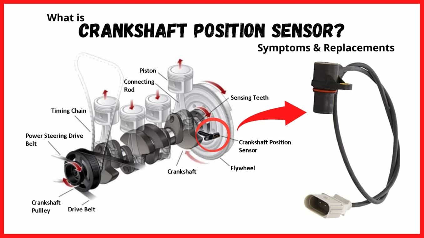
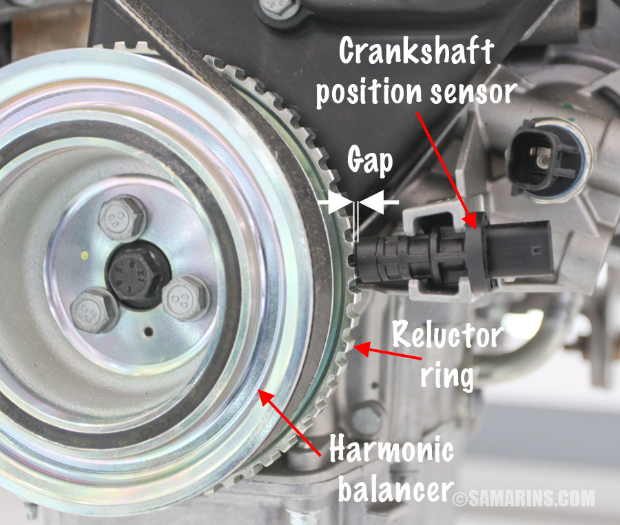
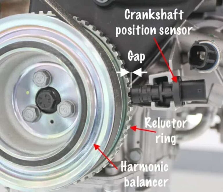
The GM crankshaft position sensor, commonly called the CKP sensor, monitors crankshaft position and rotational speed. The engine control module uses that information to determine when the engine is turning and to coordinate functions such as ignition and fuel control.
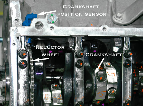
The sensor reads a rotating reluctor or tone wheel associated with the crankshaft. As the crankshaft turns, the sensor produces a changing electrical signal. The PCM interprets that signal to establish engine speed and crankshaft position.
GM has used more than one CKP sensor design across its cars, trucks, SUVs, and engines. That difference matters because the correct testing procedure, wiring arrangement, signal type, and specifications can change from one application to another.
Source: samarins.com
Two-wire magnetic sensor
A magnetic pickup generally generates an AC voltage as the reluctor passes the sensor. These sensors are commonly evaluated for coil continuity, resistance where specified, and an AC signal during cranking.
Three-wire electronic sensor
A three-wire design commonly has a power or reference circuit, a ground, and a signal circuit. Its output is typically a digital switching signal rather than the simple AC waveform produced by a passive magnetic pickup.
PCM input
The engine computer needs a usable CKP signal, not merely continuity through the sensor. A sensor can show an apparently reasonable electrical reading and still fail under operating conditions.
Before You Test the GM Crankshaft Position Sensor
Start with the vehicle information, not the meter. Write down the GM model, model year, engine size, and engine code if available. The correct connector pinout and electrical specifications are vehicle-specific.
A factory service manual or reliable service information should identify the CKP sensor terminals, circuit functions, test conditions, and expected readings. GM’s diagnostic information also shows that CKP monitoring and fault criteria vary by engine and system, so a single universal voltage or resistance value is not appropriate for every GM vehicle.
If the vehicle has a diagnostic trouble code such as P0335 or P0336, treat the code as a starting point rather than proof that the sensor itself has failed. Wiring problems, connector faults, reluctor damage, mechanical timing problems, and other circuit conditions can produce similar symptoms.
Source: autotoride.com
Digital multimeter
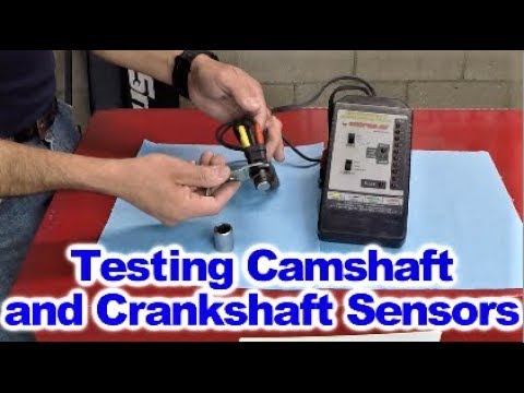
Use a quality meter that can measure resistance, DC voltage, and AC voltage. Use the correct meter function for the sensor design.
Scan tool
A scan tool capable of displaying live engine RPM can help determine whether the PCM is seeing a crankshaft signal during cranking.
Back-probing leads
Use suitable back-probing equipment when testing connected circuits. Avoid damaging terminals by forcing probes into sealed connectors.
Service information
Have the correct wiring diagram and specifications for the exact GM vehicle and engine before making a pass-or-fail decision.
Safety precautions
Park the vehicle securely, set the parking brake, and keep loose clothing, jewelry, hair, and test leads away from belts, pulleys, fans, and other moving parts. If you must crank the engine while testing, position yourself and the equipment so nothing can become caught.
Do not probe circuits randomly. Applying battery voltage to a sensor signal or reference circuit can damage electronic components. If you are unsure which terminal is which, stop and identify the circuit from the wiring diagram first.
Ignition safety
Follow the vehicle-specific procedure if ignition or fuel must be disabled for a particular test.
Hot engine parts
Allow hot components to cool when the test does not require a warm engine, and avoid exhaust components that can cause burns.
Battery condition
A weak battery can reduce cranking speed and complicate signal testing. Make sure the battery and starter can crank the engine normally.
Step 1: Check for Diagnostic Trouble Codes
Connect a compatible scan tool and retrieve stored, pending, and current diagnostic trouble codes. A GM CKP-related code can point you toward the crankshaft position circuit, but it does not automatically identify the failed component.
P0335 is commonly associated with a crankshaft position sensor A circuit problem, while P0336 can indicate a CKP performance or range problem on applications that use those codes. The exact diagnostic logic varies by GM powertrain and model year.
Record all related codes before clearing anything. A second code involving engine timing, camshaft position, power supply, or another sensor may change the diagnostic path.
Source: carinterior.alibaba.com
Record the code
Write down the complete code and its description before clearing it.
Check freeze-frame data
When available, review the engine speed, temperature, and operating conditions stored when the fault occurred.
Do not replace parts immediately
Use the code to identify the circuit or system that needs testing rather than treating the code as a parts-order instruction.
Step 2: Inspect the GM CKP Sensor and Wiring
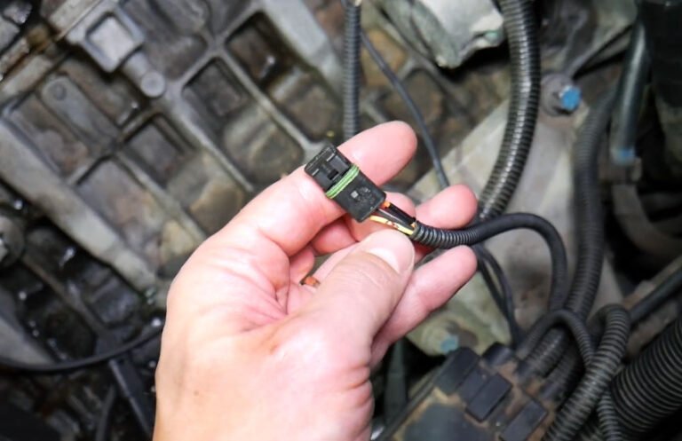
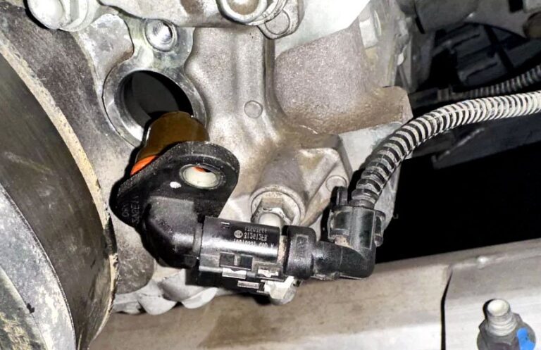
A visual inspection should come before electrical testing. Locate the CKP sensor using the vehicle-specific service information and inspect the sensor body, connector, terminals, and harness.
Look for oil contamination, corrosion, broken locks, pushed-out terminals, damaged insulation, stretched wires, and wiring that has rubbed against the engine or other components. Heat and vibration can create intermittent faults that a quick resistance check may miss.
Also inspect the sensor mounting area. A damaged sensor, incorrect installation, excessive debris, or a problem with the reluctor can prevent a correct signal even when the sensor’s internal electronics are functional.
Source: mechlesson.com
Connector terminals
Check for bent, loose, recessed, corroded, or contaminated terminals.
Harness condition
Follow the harness far enough to identify rubbing, melted insulation, broken conductors, or poor previous repairs.
Sensor mounting
Verify that the sensor is securely mounted and positioned as specified for the engine.
Reluctor area
If accessible and appropriate for the vehicle, inspect for damaged teeth, abnormal debris, or other conditions that could disturb the sensor signal.
Step 3: Identify the Sensor Type
Before connecting the multimeter, determine whether your GM vehicle uses a two-wire magnetic CKP sensor or a three-wire electronic CKP sensor. Do not assume that every GM crankshaft position sensor uses the same test.
A two-wire magnetic sensor generally produces an AC signal as the crankshaft turns. A three-wire sensor generally needs a supply or reference voltage and ground and produces a switching signal on its output circuit.
The connector appearance alone is not enough to establish the circuit functions. Use the wiring diagram for your exact vehicle to identify power, ground, and signal terminals.
Source: animalia-life.club
Two-wire design
Usually test the sensor’s resistance only when the manufacturer’s procedure calls for it, then check for an AC voltage signal while the engine is cranking.
Three-wire design
Check the power or reference circuit and ground first, then verify the signal circuit while cranking or running as directed by the service procedure.
Unknown design
Do not guess. Confirm the sensor type and terminal functions from the vehicle’s wiring information.
Step 4: Test a Two-Wire Magnetic GM CKP Sensor
For a two-wire magnetic CKP sensor, a useful sequence is visual inspection, resistance testing when specified, and AC voltage testing during cranking. The most meaningful result is whether the sensor produces the correct signal under the specified conditions.
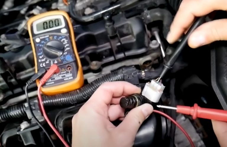
Disconnect the sensor connector before measuring resistance through the sensor. Set the multimeter to resistance and place the probes across the sensor terminals. Compare the result with the specification for the exact GM engine. A generic resistance range from another vehicle should not be used as a pass-or-fail standard.
Next, set the meter to AC voltage when the service procedure calls for an AC output test. Connect the meter to the appropriate sensor terminals and crank the engine. A changing AC signal indicates that the sensor is responding to crankshaft movement, but the exact acceptable output depends on the sensor and test conditions.
If the reading remains at zero when a signal should be present, check the connector, wiring, sensor position, reluctor condition, and cranking speed before replacing the sensor.
Source: artofit.org
Resistance is abnormal
An open circuit or a reading outside the specified range can indicate a sensor problem, but the correct specification must come from the exact GM application.
AC signal is present
A changing signal suggests that the magnetic sensor is responding, but it does not by itself prove that the waveform is correct.
No AC signal
A missing signal can result from the sensor, wiring, connector, reluctor, sensor position, or insufficient crankshaft speed.
Why resistance testing is not enough
Resistance testing checks an electrical property of the sensor coil. It does not reproduce every condition the sensor experiences while the engine turns. A sensor can pass a static resistance test and still produce an inadequate or intermittent signal.
For that reason, use resistance as one part of the diagnosis rather than the final answer. When available, a live RPM reading or oscilloscope waveform provides stronger information about the actual CKP signal reaching the engine computer.
Step 5: Test a Three-Wire GM CKP Sensor
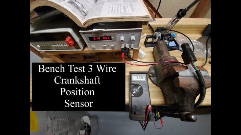
A three-wire GM crankshaft position sensor needs a different approach because it normally relies on an external electrical supply or reference and produces a digital signal. Do not perform the two-wire AC-voltage procedure on a three-wire sensor unless the service information specifically calls for it.
With the ignition on and the connector connected or disconnected as specified by the service procedure, identify the supply or reference terminal using the wiring diagram. Measure the voltage against the correct ground. Then verify the ground circuit with the appropriate voltage-drop or circuit test.
Once the supply and ground are confirmed, test the signal circuit while the engine is cranking. A digital meter may show an average or changing voltage rather than displaying the actual switching waveform. That means a meter can indicate activity without proving that the waveform has the correct shape, frequency, or amplitude.
A scope is more useful when a three-wire sensor has an intermittent fault or when the PCM reports a performance problem despite apparently normal power and ground circuits.
Source: youtube.com
Verify the supply
Confirm the expected supply or reference voltage using the correct GM wiring diagram and test procedure.
Verify ground
A poor ground can make a good sensor appear defective, so test the circuit rather than relying only on a visual inspection.
Check the signal
Look for the expected switching activity during cranking. Use a scope when the digital signal needs to be evaluated in detail.
Protect the circuit
Never short a reference, supply, ground, or signal terminal together while probing the connector.
Step 6: Check Engine RPM With a Scan Tool
A scan tool can provide one of the quickest clues about whether the PCM is receiving a usable CKP signal. Connect the scan tool, open the live-data section, and watch engine RPM while the starter cranks the engine.
If the scan tool shows no engine speed during cranking on a system that should report it, investigate the CKP circuit and related inputs. A zero RPM reading does not automatically prove the sensor is defective because wiring, power, connector, PCM input, and mechanical problems can also interrupt the signal.
If RPM appears consistently while cranking, the PCM is receiving some crankshaft speed information. That does not guarantee that the CKP signal is perfect, especially when the vehicle has an intermittent fault or a performance code. In those cases, compare live data with the service procedure and consider waveform testing.
Source: hitchesguide.com
Zero RPM during cranking
Investigate the CKP sensor circuit, connector, wiring, sensor, reluctor, and related PCM inputs before replacing parts.
Stable RPM signal
A consistent RPM signal suggests that the PCM is receiving crankshaft information, although further testing may be needed for intermittent or performance faults.
RPM suddenly drops to zero
An intermittent loss of RPM can point toward a CKP signal or circuit problem, particularly if the engine stalls at the same time.
Why scan-tool RPM is useful
The scan tool evaluates information after it reaches the vehicle’s control system. That makes it useful for separating a sensor output problem from a problem farther downstream in the circuit.
For an intermittent no-start or stall, monitoring RPM while the problem occurs can be more informative than testing a sensor after the vehicle has returned to normal operation.
Step 7: Check the CKP Signal With an Oscilloscope When Needed
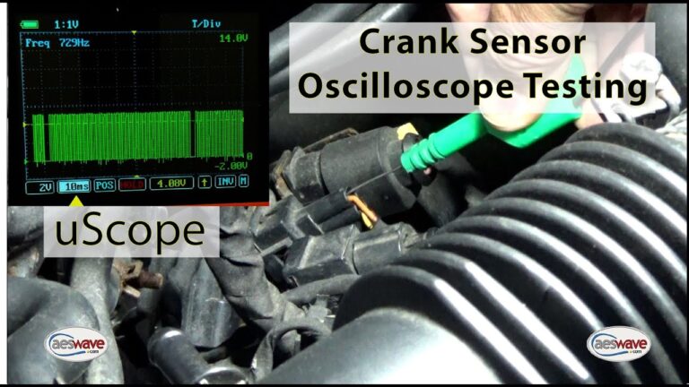
An oscilloscope is the better tool when a multimeter and scan tool do not explain an intermittent or performance-related CKP problem. A scope can display the actual waveform and show whether the signal repeats correctly as the crankshaft rotates.
For a magnetic sensor, the waveform should change as the reluctor passes the sensor. For an electronic sensor, the scope can reveal the switching pattern and identify abnormalities that a digital multimeter may hide.
A scope can also help reveal problems caused by damaged reluctor teeth, inconsistent sensor spacing, electrical interference, or intermittent wiring. The correct waveform must still be compared with the specification or known-good pattern for the particular GM engine.
Source: samarins.com
Look for consistency
The signal should repeat in a pattern that corresponds with crankshaft rotation and the engine’s reluctor design.
Look for dropouts
A sudden loss or distortion of the waveform can help identify an intermittent sensor, wiring, or reluctor problem.
Compare the pattern
Use vehicle-specific service information or a known-good waveform rather than assuming that every GM engine produces the same pattern.
How to Tell Whether the Sensor or Wiring Is Bad
A bad CKP sensor is only one possible cause of a missing or incorrect crankshaft signal. The diagnosis becomes stronger when several tests point to the same component.
For example, if the sensor has the correct supply and ground where required, the wiring is intact, the reluctor is in good condition, and the sensor produces no specified output during cranking, the sensor becomes a stronger suspect. If the sensor produces a valid signal at the sensor connector but the PCM does not see it, investigate the signal wiring and PCM-side circuit.
An intermittent fault requires extra care. A sensor may work when cold and fail when hot, or a damaged wire may open when the engine moves. Repeating the test under the conditions that trigger the symptom can be more useful than replacing a part based on a single static measurement.
Source: 1aauto.com
Sensor output missing at the sensor
If power and ground are correct where required and the sensor fails its specified output test, the sensor or its mechanical relationship with the reluctor deserves close attention.
Signal present at the sensor but absent at the PCM
This points toward the signal circuit, connector, terminal, or related wiring rather than automatically proving the sensor is bad.
Power or ground missing
Repair the circuit problem before replacing a three-wire electronic sensor.
Signal changes with harness movement
An intermittent harness or terminal problem becomes more likely when a controlled wiggle test reproduces the fault.
Common symptoms of a CKP signal problem
A CKP problem can cause a crank-no-start condition, extended cranking, intermittent stalling, an erratic or missing RPM reading, or a check-engine light. The symptoms are not unique to the crankshaft position sensor, so they should be combined with electrical and scan-tool evidence.
GM diagnostic systems monitor crankshaft synchronization and signal performance in different ways depending on the engine and model year. That is another reason to diagnose the actual circuit rather than relying on a symptom checklist alone.
Engine cranks but does not start
A missing CKP signal can prevent the PCM from establishing the crankshaft position needed for normal engine control.
Intermittent stalling
An intermittent CKP signal loss can cause the engine to stop and may allow it to restart after the fault disappears.
No or erratic RPM data
An abnormal scan-tool RPM signal during cranking can support further CKP circuit testing.
Common Mistakes When Testing a GM Crankshaft Position Sensor
The most common diagnostic mistake is treating a generic test value as universal. GM has used multiple CKP sensor designs and engine configurations, so the correct value and test procedure depend on the vehicle.
Another mistake is replacing the sensor immediately after seeing a P0335 or similar code. The code identifies a monitored circuit or performance condition. It does not necessarily identify the failed physical part.
Finally, do not overlook the mechanical side. A good sensor cannot produce the correct relationship to the PCM if the reluctor or related crankshaft components are damaged or incorrectly positioned.
Source: artofit.org
Using the wrong meter setting
A magnetic sensor signal may require AC voltage testing, while a three-wire electronic sensor produces a different type of signal.
Testing the wrong pins
Always identify terminal functions from the correct wiring diagram before applying test leads.
Relying only on resistance
Resistance can identify certain failures but cannot fully verify a dynamic CKP signal.
Ignoring the harness
A damaged connector or intermittent wire can create the same symptoms as a defective sensor.
Skipping the reluctor inspection
The sensor depends on the crankshaft’s reluctor pattern, so mechanical damage can create a signal problem even with a new sensor.
What to Do If the Test Fails
If the CKP test fails, do not immediately install another sensor. First identify exactly which part of the diagnostic chain failed: sensor output, power, ground, signal wiring, connector, reluctor, or PCM input.
If the sensor has no output, verify that the test conditions and sensor type are correct. If a three-wire sensor lacks its required supply or ground, repair that circuit first. If the signal reaches the PCM but the PCM reports an abnormal pattern, investigate the waveform, reluctor, wiring, and applicable GM diagnostic information.
If the engine has a persistent no-start condition and the electrical tests do not identify the cause, other systems may also need testing. Fuel pressure, ignition, camshaft position, engine timing, compression, and PCM-related faults can produce similar symptoms.
Source: animalia-life.club
Repair wiring first
Do not replace a sensor to compensate for an open, shorted, corroded, or poorly connected circuit.
Confirm the replacement part
If replacement is justified, verify the correct part number and application using the vehicle identification information.
Clear codes only after diagnosis
After repairs, clear codes according to the appropriate procedure and verify whether the fault returns under the conditions that originally caused it.
Seek professional diagnosis when necessary
A professional technician is appropriate when access is difficult, waveform testing is required, the wiring diagram is unclear, or the engine has a complex intermittent fault.
Frequently Asked Questions
Q
How do I test a GM crankshaft position sensor with a multimeter?
First identify whether the GM vehicle uses a two-wire magnetic sensor or a three-wire electronic sensor. A two-wire sensor may be checked for resistance and an AC signal during cranking when specified, while a three-wire sensor normally requires supply, ground, and signal testing.
Use the exact specifications and terminal identification for the vehicle. A generic resistance or voltage value should not be used as a universal GM standard.
Q
What voltage should a GM crankshaft position sensor have?
There is no single voltage that applies to every GM crankshaft position sensor. The expected voltage depends on the sensor design and engine application.
A two-wire magnetic sensor generates its own changing AC signal, while many three-wire electronic sensors use an external supply or reference and produce a switching signal. Check the exact GM wiring diagram and service specification before judging the reading.
Q
Can a GM crankshaft position sensor be bad without setting a code?
Yes. An intermittent CKP problem may occur under conditions that are not captured consistently by the diagnostic monitor. Wiring faults and signal dropouts can also be difficult to reproduce during a stationary test.
If the vehicle intermittently stalls or loses RPM information, monitor live data or the CKP waveform while the fault occurs rather than relying only on stored codes.
Q
Does P0335 always mean the GM crankshaft position sensor is bad?
No. P0335 identifies a crankshaft position sensor A circuit condition, but the underlying cause can involve the sensor, wiring, connector, power or ground circuit, reluctor, or another related problem depending on the vehicle.
Diagnose the circuit and signal before replacing the sensor.
Q
What should the RPM reading be while cranking a GM engine?
The expected cranking RPM depends on the engine, battery condition, starter, temperature, and other factors. More important than using a universal number is whether the scan tool shows a stable crankshaft-derived RPM signal while the starter turns the engine.
If the scan tool shows zero RPM during normal cranking, investigate the CKP circuit and related systems.
Q
Can a bad crankshaft position sensor cause a GM vehicle to crank but not start?
Yes. If the PCM does not receive the crankshaft position information it needs, the engine may crank without starting. However, a crank-no-start condition has many possible causes.
Confirm the CKP signal and then continue testing fuel, ignition, camshaft synchronization, engine timing, and other relevant systems if the CKP circuit checks out.
Q
Should I replace the crankshaft position sensor if resistance is out of specification?
If the resistance test is specifically required for your GM sensor and the measured value clearly falls outside the manufacturer’s specification, the sensor becomes a strong suspect. Confirm the test conditions and measurement method first.
Also inspect the connector and wiring because a circuit problem can affect the reading.
✦ Wrapping Up
Conclusion
The most reliable way to test a GM crankshaft position sensor is to follow a complete diagnostic sequence rather than relying on one multimeter reading. Start with trouble codes and a visual inspection, identify the exact sensor design, verify the circuit, and then test the CKP signal under the correct cranking or running conditions.
For two-wire magnetic sensors, resistance and AC signal tests can provide useful information when performed according to the vehicle’s specifications. For three-wire electronic sensors, verify the required supply and ground and evaluate the signal circuit. A scan tool showing engine RPM and an oscilloscope waveform can provide additional evidence when a basic multimeter test does not explain the problem.
If the sensor appears to work but the vehicle still loses synchronization, investigate the wiring, connectors, reluctor, mechanical timing, and PCM-side circuit before installing another part. The goal is to identify the failed part or circuit, not simply to replace the component associated with a diagnostic code.
💡 Key Takeaway
For an accurate GM crankshaft position sensor diagnosis, identify your exact engine and sensor type first, then compare power, ground, resistance, signal, and scan-tool RPM results with the correct GM service specifications.
Ethan Brooks is an automotive writer at Auto News 7, covering car news, vehicle maintenance, new model updates, recalls, and practical buying guides. He focuses on clear, useful information that helps drivers understand their vehicles and make better ownership decisions.
Learn how to install crankshaft position sensor correctly with step-by-step instructions, tools, safety tips, troubleshooting advice, and signs of a successful installation.
Learn how to replace a crankshaft position sensor with a detailed step-by-step guide, tools list, troubleshooting tips, safety advice, and signs of a successful repair.