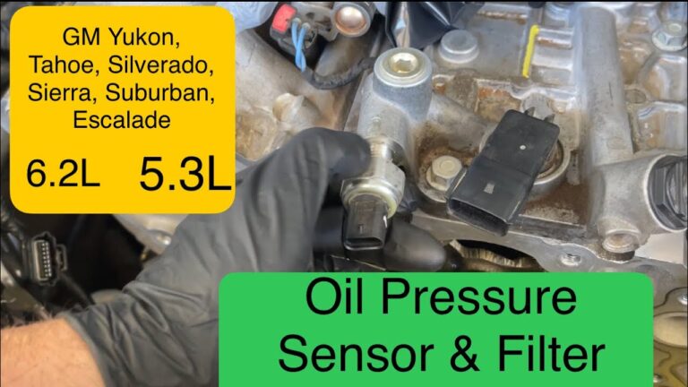
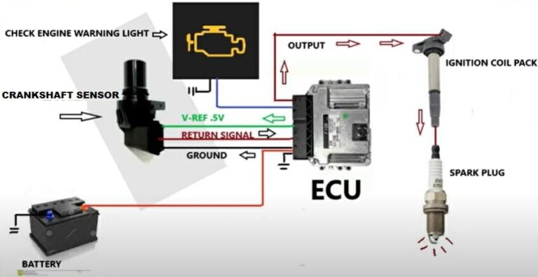
To ground an oil pressure sensor, restore its specified ground path through the sensor body or dedicated ground wire, then verify the circuit.
For vehicles sold and serviced in the United States, the correct way to ground an oil pressure sensor depends on the sensor design and the vehicle wiring diagram. Some one-terminal oil pressure senders ground through their threaded metal body and engine block. Modern electronic oil pressure sensors commonly use a dedicated ground terminal in the wiring harness.
Do not assume every oil pressure sensor should be connected directly to the chassis. A factory sensor may use a dedicated sensor-ground circuit that returns to the engine control module. Adding a jumper to the wrong terminal can create a short circuit or an incorrect pressure signal. Before making any connection, identify the sensor type and confirm the terminal assignments for the exact vehicle.
Source: carsensorhub.com
Identify How Your Oil Pressure Sensor Grounds
The first step in learning how to ground oil pressure sensor wiring is identifying the sensor’s electrical design. The most common arrangements are a one-terminal sender that grounds through its body and a multi-terminal sensor with a dedicated ground circuit.
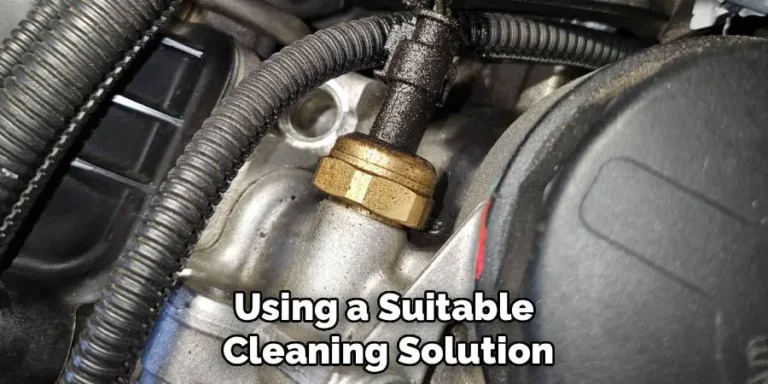
A one-terminal pressure sender normally uses the metal sender body as part of the electrical return path. When the sender is threaded directly into a grounded engine component, the metal threads and engine provide the return path. A remote-mounted sender may need a separate ground connection if its mounting arrangement does not provide electrical continuity.
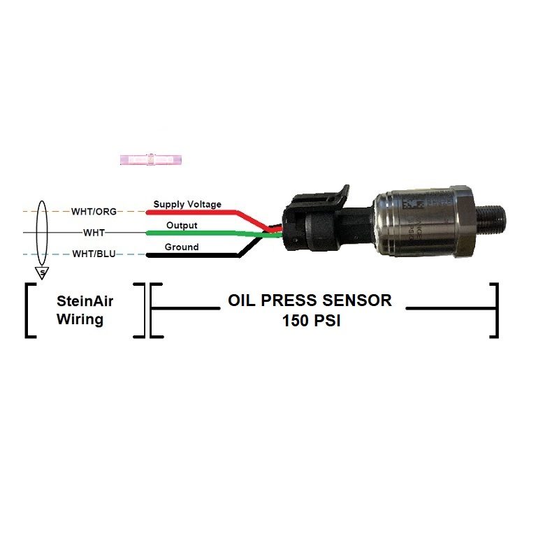
A modern electronic pressure sensor can have power, signal, and ground terminals. In that design, the ground is normally a specific wire in the harness. The correct ground point is determined by the vehicle’s wiring diagram, not simply by whichever chassis bolt is closest.
Source: storage.googleapis.com
One-terminal sender
The sender body commonly provides the ground path through its threaded connection to the engine or another grounded engine component.
Two-terminal switch or sender
One terminal may carry the signal while the second provides ground, although some designs still use the body as the ground path.
Three-terminal electronic sensor
The sensor commonly has separate power, signal, and ground circuits. Follow the vehicle-specific wiring diagram for terminal identification.
Why the sensor type matters
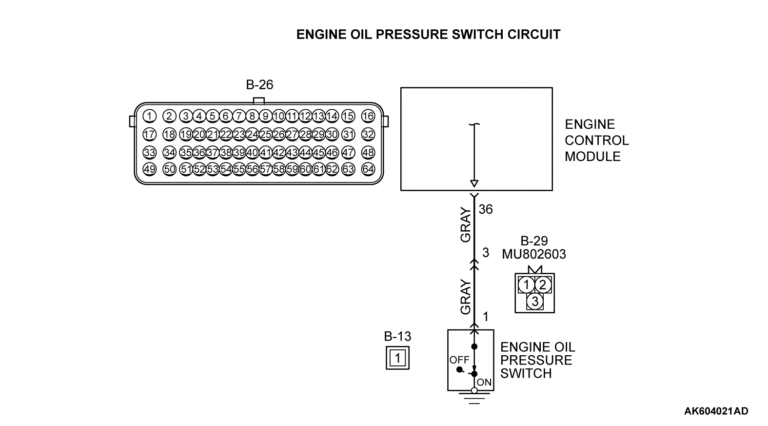
Grounding methods are not interchangeable. Service information for electronic oil pressure sensors can specify a dedicated sensor-ground circuit between the sensor connector and the engine control module. Other oil pressure switches are designed to return through the engine block. Using the wrong method can create a diagnostic fault even when the sensor itself is good.
Check the connector
Count the terminals and inspect the connector before making any wiring changes.
Check the wiring diagram
Confirm which terminal is ground and where that circuit is supposed to return.
What You Need Before Grounding the Sensor
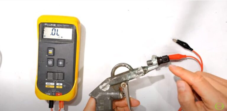
Gather the basic tools before working on the oil pressure sensor. A digital multimeter is the most useful tool because it can check continuity, resistance, and voltage. You may also need the vehicle’s service information or wiring diagram to identify the correct ground terminal.
Park the vehicle on a stable surface, switch the ignition off, and allow hot engine components to cool before working around the sensor. Keep loose clothing, tools, and wiring away from belts, fans, and other moving parts when the engine must be running for a voltage test.
If the sensor is located near the oil filter, exhaust, starter, or other components, make sure you can access the connector without pulling or twisting the wiring harness.
Source: storage.googleapis.com
Digital multimeter
Use a quality meter that can measure resistance and DC voltage.
Vehicle-specific wiring information
Use the correct diagram to identify the sensor ground circuit and connector terminals.
Basic hand tools
Have the tools required to remove a connector, clean a ground point, or access the sensor without damaging nearby components.
Electrical contact cleaner
Use an appropriate electrical contact cleaner when connector contamination is found, following the product and vehicle instructions.
How to Ground Oil Pressure Sensor Step by Step
The safest procedure is to identify the intended ground path, inspect it, test it, and repair only the fault that the test identifies. Do not begin by connecting a random wire from the sensor to the battery negative terminal.
First, turn the ignition off and locate the oil pressure sensor. Disconnect the electrical connector if the vehicle service procedure allows it. Inspect the connector for loose terminals, corrosion, oil contamination, damaged insulation, or a terminal that has been pushed backward inside the connector.
Next, determine whether the sensor grounds through its body or through a dedicated terminal. If the sensor uses a dedicated ground wire, use the wiring diagram to identify that terminal. If the sender grounds through its body, inspect the threaded mounting area and the engine-side contact surface.
For a body-grounded sender, verify that the metal body has a sound electrical path to engine ground. For a dedicated ground circuit, test continuity between the specified sensor-ground terminal and the designated ground point or control-module terminal with the circuit powered down.
If the ground path is open or has excessive resistance, repair the damaged wire, terminal, connector, or grounding connection. If the ground path tests correctly, do not add another ground wire simply because the oil pressure reading is incorrect. Continue diagnosing the power, signal, sensor, and actual oil pressure.
Source: storage.googleapis.com
Step 1: Turn the ignition off
Prevent accidental electrical shorts while inspecting or disconnecting the sensor.
Step 2: Locate the sensor
Use the vehicle service information because sensor locations vary by engine and model.
Step 3: Identify the ground design
Determine whether the sensor grounds through its body or through a dedicated electrical terminal.
Step 4: Inspect the connection
Look for corrosion, damaged terminals, loose connectors, broken wires, contamination, or poor metal-to-metal contact.
Step 5: Test the ground
Use the wiring diagram and multimeter to verify that the specified ground path is electrically sound.
Step 6: Repair the actual fault
Restore the factory ground path rather than adding an unverified jumper.
Step 7: Reconnect and retest
Reconnect the sensor, clear any applicable diagnostic faults, and verify the oil pressure signal according to the vehicle service procedure.
Grounding a one-terminal oil pressure sender
A one-terminal sender commonly grounds through its metal housing. If it is threaded directly into a suitable engine passage, the threaded metal connection can provide the electrical return path. If the sender is mounted remotely with an electrically insulating hose, gasket, bracket, or fitting, the body may no longer have a reliable ground.
In a remote installation, use the sender manufacturer’s specified grounding method. Some sender manufacturers require a ground wire from the sender body or mounting bracket to a suitable ground. Do not assume a painted or powder-coated bracket provides a reliable electrical connection.
Inspect the threads and mounting surface
Confirm that the design provides the intended electrical connection and that corrosion or contamination is not interrupting it.
Be careful with thread sealant
Do not add insulating sealant or tape unless the sensor manufacturer specifies it. Some sealants can interfere with a body-grounded sender.
Grounding a multi-wire oil pressure sensor
A multi-wire sensor should be treated as an electronic circuit rather than as a simple body-grounded switch. The correct ground terminal must be connected to the specified sensor-ground circuit. Service information for some vehicles identifies a separate ground circuit that runs between the sensor and the engine control module.
With the sensor disconnected and the ignition off, test the specified ground circuit according to the vehicle’s diagnostic procedure. If the circuit is open or has excessive resistance, inspect the harness and connector before replacing the sensor.
Do not guess the ground terminal
Terminal positions and wire colors vary between manufacturers and engine families.
Avoid shorting the signal circuit
Connecting the signal wire to ground can produce a false reading or a diagnostic trouble code.
How to Test the Oil Pressure Sensor Ground
A grounding repair is successful only when the specified electrical path is restored and the sensor produces the expected signal. The exact test values depend on the vehicle and sensor, so use manufacturer specifications instead of a universal resistance number.
For a body-grounded sender, disconnect the electrical connector and use the multimeter to check electrical continuity between the metal sender body and a known-good engine ground. The ignition should be off for a basic continuity check. If the reading is unstable or unexpectedly high, inspect the mounting connection, corrosion, sealant, and engine ground path.
For a dedicated sensor-ground circuit, identify the correct ground terminal from the wiring diagram. With the sensor disconnected and the appropriate circuit conditions established, check the ground circuit as directed by the service procedure. Some manufacturer procedures use resistance checks, while others may require voltage or voltage-drop testing.
A voltage-drop test can be useful when a circuit appears connected but performs poorly under load. A high voltage drop across a ground connection indicates unwanted resistance in the path. Follow the vehicle’s diagnostic procedure for the correct test setup and acceptable limit.
Do not interpret a good ground test as proof that the engine has adequate oil pressure. The electrical ground only allows the sensor or switch to operate correctly. Actual oil pressure is a separate mechanical condition that may require a mechanical pressure gauge for confirmation.
Source: educationsurvey.steelcase.com
Good ground path
The measured circuit agrees with the vehicle manufacturer’s specified electrical condition.
Open ground circuit
The specified ground path is interrupted by a broken wire, disconnected terminal, failed connector, or poor mounting connection.
High-resistance ground
The circuit is connected but has unwanted resistance caused by corrosion, damaged wiring, loose terminals, or a poor grounding point.
Correct ground but wrong reading
If the ground is good, investigate the sensor, power supply, signal circuit, wiring, instrument cluster, control module, or actual oil pressure as appropriate.
Why a continuity test is not always enough
A continuity test can show that two points are electrically connected without proving that the connection works correctly under operating conditions. A weak connection may pass a basic meter test but develop an unacceptable voltage drop when current flows. For electronically controlled sensors, use the manufacturer’s diagnostic sequence rather than relying on a generic continuity reading.
Use the specified test
Follow the service procedure for resistance, voltage, or voltage-drop testing.
Check the whole circuit
A sensor-ground fault can occur at the sensor connector, harness, splice, ground point, or control-module connection.
Common Oil Pressure Sensor Grounding Problems
Most grounding problems come from a damaged electrical path rather than from the sensor suddenly needing an extra ground wire. Inspect the connector and wiring before modifying the circuit.
Corrosion is a common concern at exposed connectors and ground points. Oil contamination can also affect connectors and insulation. A broken wire inside the insulation can be difficult to see, particularly where the harness bends near the engine.
A body-grounded sender can also lose its electrical return when it is installed in a way that isolates the metal body from the engine. Remote mounting is a common example. In that situation, the manufacturer’s grounding instructions determine whether a separate ground wire is required.
Thread sealant deserves special attention. Some installations require sealing material, while others rely on metal-to-metal contact for grounding. Using a heavy layer of electrically insulating material on a body-grounded sender can interfere with the intended return path.
Source: tools.couchsurfing.com
Corroded connector
Oxidation or contamination can increase resistance or interrupt the ground circuit.
Broken ground wire
A damaged harness can create an open or intermittent sensor-ground circuit.
Poor engine ground
A damaged engine-to-chassis ground connection can affect electrical systems that depend on the engine as a reference.
Insulated sender mounting
A remote sender may lose its body-ground path when mounted with nonconductive materials.
Incorrect wiring repair
A ground jumper connected to a signal or power terminal can create a short or incorrect sensor output.
Do not ground the sensor just because the warning light is on
An oil pressure warning light or low pressure reading can result from an electrical fault, a failed sensor, a wiring problem, or genuinely low engine oil pressure. Adding a ground wire without testing can hide the original problem or create a new one.
If the oil pressure warning remains on while the engine is running, treat the condition seriously. Check the oil level and follow the vehicle’s diagnostic procedure. If actual oil pressure is suspected to be low, avoid continued engine operation until the condition has been properly evaluated.
Warning light remains on
Do not assume the sensor ground is the cause. Confirm the electrical circuit and actual oil pressure when required.
Gauge reads incorrectly
Check sensor type, power, ground, signal wiring, and sender specifications before replacing or rewiring components.
When to Stop and Get Professional Help
Stop the repair and obtain qualified automotive help when the wiring diagram is unavailable, the sensor terminals cannot be identified confidently, or the circuit involves an engine control module that you are not equipped to diagnose. Modern sensor circuits can use low-voltage reference and signal circuits that are sensitive to incorrect connections.
Professional diagnosis is also appropriate when an oil pressure warning remains active after the electrical circuit tests correctly. A mechanical oil pressure problem can cause serious engine damage if the vehicle continues to operate with inadequate lubrication.
Do not bypass an oil pressure warning system as a permanent repair. The purpose of the sensor or switch is to provide information about engine lubrication status. A jumper that forces a warning light off can remove an important warning without fixing the underlying fault.
Source: www.youtube.com > Course Solutions
Use the correct service information
Vehicle-specific terminal assignments and test procedures take priority over generic wiring advice.
Protect the control module
Avoid applying battery voltage to a sensor signal or ground terminal unless the service procedure explicitly requires it.
Confirm mechanical oil pressure when needed
An electrical repair cannot prove that the engine’s lubrication system is producing adequate oil pressure.
Repair intermittent faults
If the sensor works only when the harness is moved, inspect for damaged wires, loose terminals, or poor connector retention.
Signs the grounding repair worked
A successful repair restores the specified ground circuit without creating new diagnostic faults. The sensor or switch should then respond according to the vehicle’s normal operating strategy, and any applicable warning or gauge behavior should match the service specifications.
If the electrical ground is confirmed but the pressure reading remains abnormal, continue with the manufacturer’s diagnostic sequence instead of repeatedly changing the ground connection.
Stable electrical readings
The ground circuit remains within the manufacturer’s specified test condition.
Normal sensor operation
The oil pressure signal or switch behavior responds as specified for the vehicle.
No new electrical faults
The repair does not create a short, open circuit, or new diagnostic trouble code.
Frequently Asked Questions
Q
Does an oil pressure sensor need a ground wire?
Not always. Some oil pressure senders ground through their metal body and threaded connection to the engine. Many modern electronic sensors use a dedicated ground terminal in the wiring harness.
Check the exact sensor and vehicle wiring diagram before adding a ground wire.
Q
Can I ground an oil pressure sensor to the battery negative terminal?
A temporary diagnostic connection may be useful in some systems, but it should not replace the factory ground circuit unless the manufacturer specifically permits that repair. A dedicated sensor-ground circuit may return to the engine control module rather than directly to the battery.
Use the vehicle’s wiring diagram to determine the correct permanent ground path.
Q
Can Teflon tape prevent an oil pressure sender from grounding?
It can interfere with grounding on some body-grounded senders because the threaded connection may be part of the electrical return path. However, sealing requirements vary by sensor and engine design.
Do not remove or add thread sealant based only on a generic rule. Follow the sender and vehicle manufacturer’s installation instructions.
Q
How do I know if my oil pressure sensor ground is bad?
Inspect the connector, wiring, sensor mounting, and ground point for corrosion, damage, looseness, or contamination. Then test the specified ground circuit with a multimeter using the vehicle’s diagnostic procedure.
An open circuit or excessive resistance can indicate a grounding fault. If the ground tests correctly, investigate the power, signal, sensor, control module, and actual oil pressure as appropriate.
Q
Will a bad ground cause an oil pressure warning light to come on?
Yes, a grounding problem can cause an oil pressure switch or sensor to produce an incorrect electrical signal. The exact symptom depends on the circuit design and how the vehicle interprets the signal.
A warning light can also indicate genuinely low oil pressure or another fault, so do not assume the ground is responsible without testing.
Q
Should I keep driving if the oil pressure warning stays on?
Do not continue normal driving until the cause has been determined. A warning that represents genuinely low oil pressure can indicate inadequate engine lubrication and may lead to severe damage.
Check the oil level and follow the vehicle manufacturer’s diagnostic procedure. If actual oil pressure is uncertain, have it tested with the appropriate equipment.
✦ Wrapping Up
Conclusion
Learning how to ground oil pressure sensor circuits starts with identifying the sensor design. A body-grounded sender depends on a conductive mounting path, while an electronic sensor may require a dedicated ground wire that connects to a specific circuit in the vehicle harness.
The safest repair is to restore the factory-specified ground path and verify it with the correct electrical test. Inspect connectors and wiring before replacing parts, and never use an improvised ground connection to conceal an unresolved oil pressure problem.
💡 Key Takeaway
Identify the sensor terminals from the vehicle-specific wiring diagram, inspect the ground path, test it with a multimeter, repair only the confirmed fault, and verify actual oil pressure when the warning or reading remains abnormal.
Ethan Brooks is an automotive writer at Auto News 7, covering car news, vehicle maintenance, new model updates, recalls, and practical buying guides. He focuses on clear, useful information that helps drivers understand their vehicles and make better ownership decisions.
Learn how to disconnect an oil pressure sensor safely, identify the connector, release the locking tab, avoid damage, and troubleshoot common problems.
Learn how to wire a crankshaft position sensor safely, identify sensor wires, connect 2-wire and 3-wire sensors, test circuits, and fix common wiring faults.
Learn how to test an oil pressure sensor with a multimeter and mechanical gauge, identify wiring faults, and separate sensor problems from real low oil pressure.