Replace damaged oil pressure sensor wiring by matching the factory circuit, repairing the harness correctly, and testing it before driving.
For drivers and DIY mechanics in the United States, oil pressure sensor wiring is part of the engine monitoring circuit that can trigger an oil pressure warning or send pressure information to the vehicle computer. A damaged wire, loose terminal, corroded connector, or short circuit can create a false warning or prevent the vehicle from reporting a real oil pressure problem.
Learning how to replace oil pressure sensor wiring starts with diagnosis rather than cutting wires immediately. Vehicle circuits differ by make, model, engine, and sensor type. Factory wiring information should therefore determine the wire location, terminal position, circuit function, and repair method for the specific vehicle.
The general process is to identify the damaged section, disconnect power when appropriate, expose the harness, replace the damaged wire or connector with the correct components, protect the repair from heat and moisture, and verify continuity or voltage according to the vehicle service information. If the oil pressure warning remains on after the wiring repair, the problem may be the sensor, instrument system, control module, or actual engine oil pressure rather than the wiring.
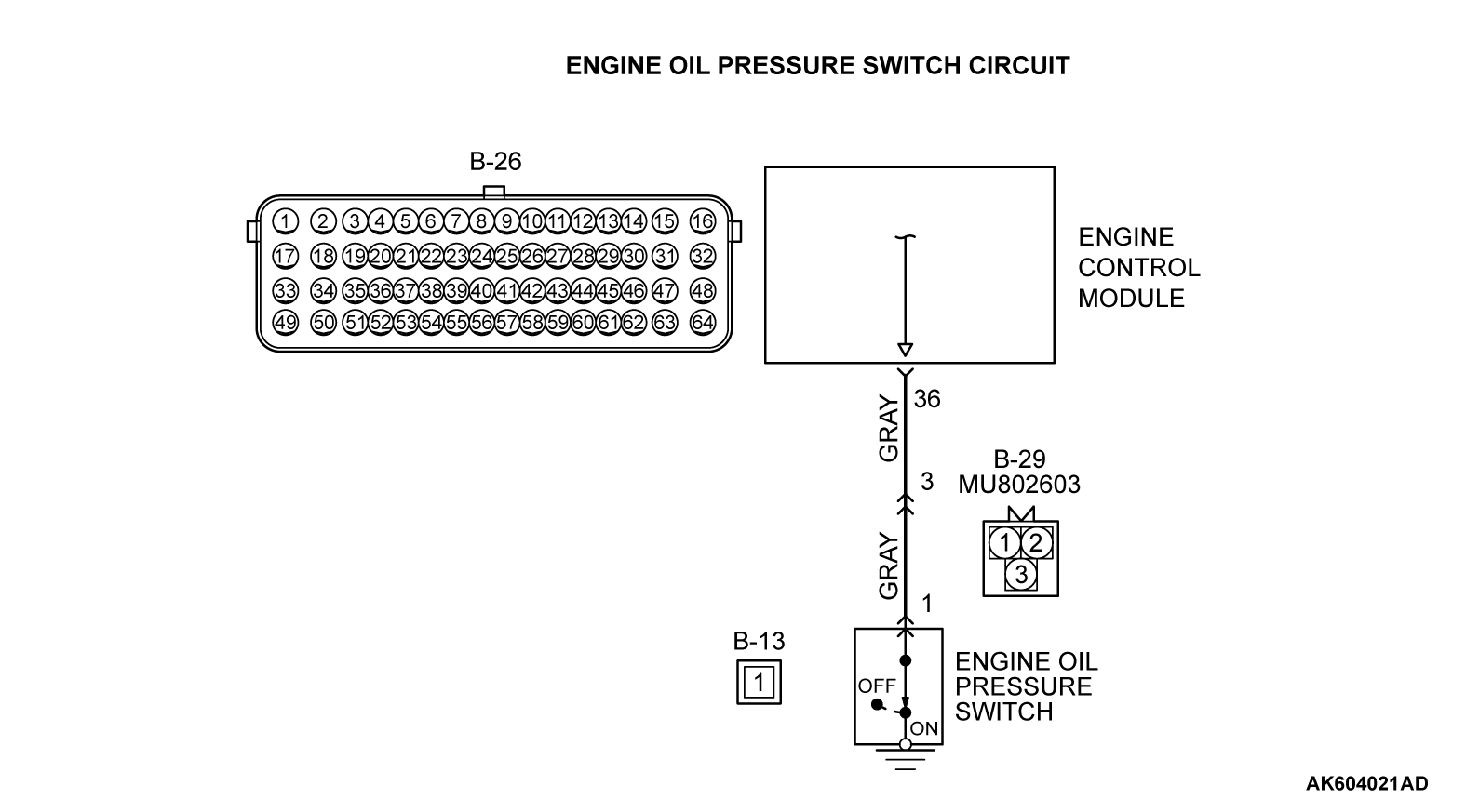
Source: mitsubishitechinfo.com
What Does Oil Pressure Sensor Wiring Do?
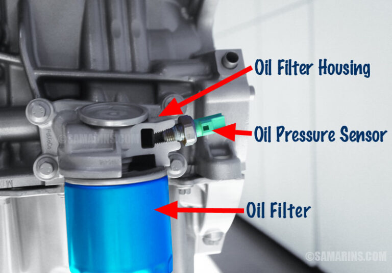
Oil pressure sensor wiring connects the oil pressure sensor or switch to the vehicle’s monitoring system. Depending on the vehicle, that system may include the engine control module, body or power distribution electronics, instrument cluster, or another control unit.
Not every vehicle uses the same type of oil pressure circuit. Some systems use a simple pressure switch that changes circuit state when pressure reaches a specified level. Other vehicles use a pressure sensor that provides a variable electrical signal. The correct test procedure therefore depends on the vehicle.
A factory service procedure may call for continuity testing between the sensor connector and a control-module connector. Other systems require a voltage check at the sensor connector or a scan-tool data check. These differences are why wire colors and generic pinout diagrams should not replace the vehicle’s specific wiring information.
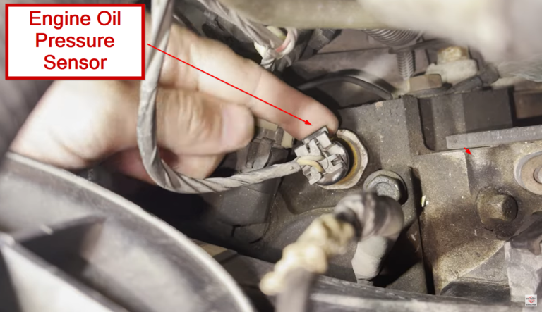
Source: i.pinimg.com
Sensor or switch
The oil pressure component detects or responds to engine oil pressure and provides an electrical signal to the vehicle system.
Wiring harness
The harness carries electrical power or the pressure signal between the sensor circuit and the appropriate vehicle electronics.
Connector
The connector provides a removable electrical connection and must maintain secure terminal contact.
Control system
The control module, warning circuit, or instrument cluster interprets the signal and may illuminate the oil pressure warning indicator.
When Should the Wiring Be Replaced?
Replace or repair the wiring when inspection shows an open circuit, short circuit, broken conductor, severe corrosion, melted insulation, damaged terminals, or another fault that prevents the circuit from operating correctly. A wire that is only lightly scuffed may not need complete replacement if the conductor and insulation can be safely restored according to an appropriate automotive repair procedure.
Do not assume the wire is the cause simply because the oil pressure warning light is on. Low oil level, actual low oil pressure, a defective sensor or switch, a damaged connector, and control-system faults can produce related symptoms.
Broken conductor
A conductor that has separated can create an open circuit and prevent the sensor signal from reaching the monitoring system.
Short circuit
A damaged wire touching ground or another circuit can alter the expected sensor signal.
Heat damage
Melted insulation near the exhaust or another heat source can expose the conductor and create an intermittent or permanent fault.
Tools and Parts Needed for the Repair
The exact tools depend on where the damage is located and how the vehicle manufacturer specifies harness repairs. Gather the vehicle’s wiring diagram or factory service information before cutting the harness. This lets you identify the correct circuit instead of relying only on wire color.
For a typical wiring repair, you may need a digital multimeter, suitable wire strippers, terminal tools, an appropriate replacement wire, automotive-grade splice components, heat-shrink protection, electrical tape for harness wrapping where appropriate, and replacement connector terminals or a pigtail if the connector is damaged.
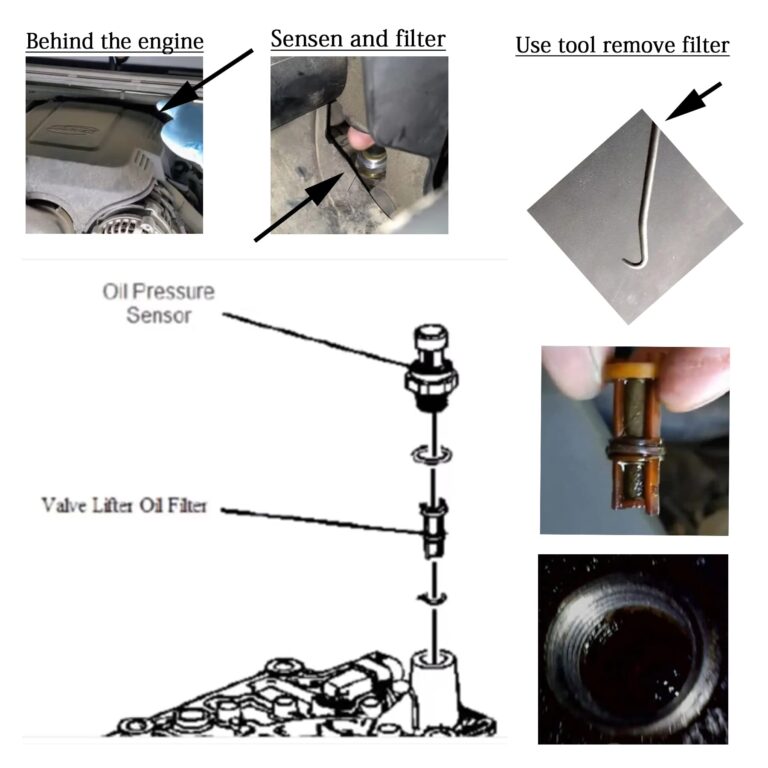
If the sensor itself must be removed during diagnosis, use the correct socket or wrench and follow the vehicle’s service procedure. Some sensors are installed in locations where oil can escape when the component is removed, so protect the work area and check the oil level afterward.
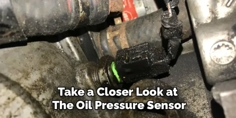
Source: uchanics.ca
Digital multimeter
Use it to perform the voltage, continuity, resistance, and short-circuit checks specified for the vehicle.
Correct replacement wire
Use a wire with suitable conductor size, insulation type, temperature capability, and construction for the application.
Automotive splice or connector
Use a repair method designed for vehicle wiring and appropriate for the circuit’s environment.
Heat protection
Use suitable heat-shrink or harness protection to help seal and mechanically protect the repaired area.
Safety Before Starting
Park on a stable surface, switch the ignition off, and allow hot engine components to cool before working near the engine. Keep loose clothing, tools, and wiring away from belts, fans, pulleys, and other moving components.
Disconnect the negative battery cable when the vehicle’s service procedure calls for it and when doing so will not create another issue, such as loss of required settings. Some modern vehicles have specific battery-disconnection procedures, so follow the manufacturer’s instructions.
Do not work around a running engine unnecessarily
Many wiring inspections can be completed with the engine off. Use the manufacturer’s procedure when a running-engine test is specifically required.
Avoid guessing terminal functions
A similar-looking connector or wire color does not prove that the circuit has the same function.
How to Replace Oil Pressure Sensor Wiring Step by Step
The safest approach is to diagnose the circuit first and repair only the damaged portion that the service information permits. The following procedure is a general framework. Use the exact connector locations, terminal numbers, testing values, and repair instructions for your vehicle.
Source: b.fridayparts.com
1. Confirm the symptom
Check the oil level and inspect the oil pressure warning behavior. If the warning indicates possible low oil pressure while the engine is running, do not continue driving until actual oil pressure has been evaluated.
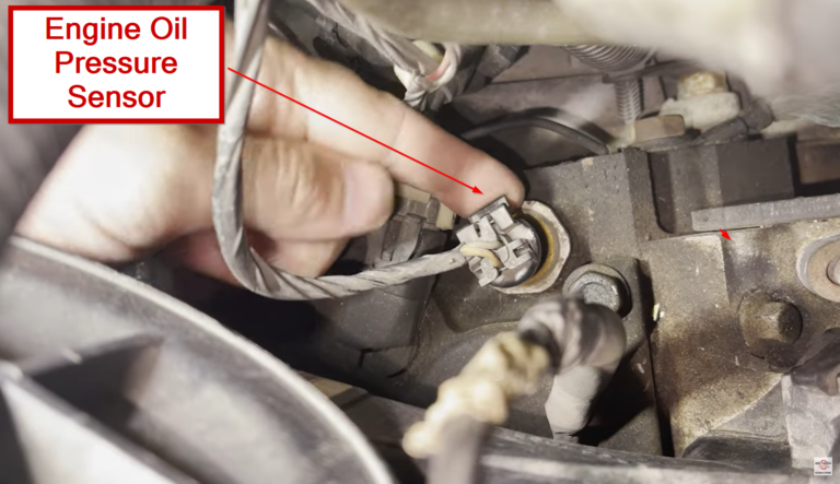
2. Inspect the sensor and connector
Look for loose terminals, broken locks, corrosion, oil contamination, damaged insulation, pulled wires, and evidence of heat or rubbing.
3. Trace the harness
Follow the sensor wiring from the connector toward the next connector or control module. Look for areas where the harness contacts brackets, engine components, exhaust parts, or sharp edges.
4. Test the circuit
With the relevant connectors disconnected, perform the continuity and short-circuit checks specified by the service information. A circuit that fails the prescribed test needs repair before replacing other components.
5. Disconnect the damaged section
If the repair procedure permits wire replacement or splicing, remove the damaged section while preserving enough wire for a secure repair. Do not remove a large section unnecessarily.
6. Prepare the replacement wire
Match the original circuit’s conductor size and use suitable automotive-grade wire. Keep the replacement section long enough to avoid tension but short enough to maintain the original harness routing.
7. Make the electrical connection
Use the splice method specified or approved for the vehicle. The connection should be mechanically secure and electrically sound. Do not simply twist wires together and cover the joint with tape.
8. Protect and route the repair
Seal and protect the repaired section as appropriate. Recreate the original harness routing and retain the wiring away from heat, moving components, sharp edges, and areas where it can be pulled or rubbed.
9. Repair the connector if necessary
If the terminal or connector housing is damaged, replace the affected terminal, connector, or pigtail using the correct parts and terminal procedure rather than forcing the old connection to work.
10. Retest the circuit
Repeat the required continuity, voltage, resistance, or short-circuit checks after the repair. The repaired circuit should meet the vehicle manufacturer’s specified test conditions.
11. Reconnect everything
Reconnect the sensor, harness connectors, and battery if it was disconnected. Make sure each connector is fully seated and locked.
12. Verify operation
Turn the ignition on and observe the oil pressure warning system. Start the engine only when it is safe to do so and verify that the warning behaves according to the vehicle’s normal operating sequence.
How to Check for an Open or Shorted Wire
A basic continuity test can help locate an open circuit, but it must be performed with the circuit isolated according to the service procedure. Disconnecting both ends of the circuit prevents other vehicle components from affecting the measurement.
A short-to-ground check is also important. A wire can have continuity from end to end and still be damaged if it is unintentionally connected to ground or another circuit. Factory procedures may specify exactly which terminals to test and what result is expected.
Open circuit
The intended electrical path is interrupted somewhere between the sensor connector and the other circuit connection.
Short to ground
The signal or power wire is unintentionally connected to vehicle ground.
Short to another circuit
Two separate circuits are unintentionally connected, which can produce incorrect readings or additional electrical faults.
How to Replace a Damaged Oil Pressure Sensor Connector
If the wire is intact but the connector is cracked, melted, corroded, or unable to hold its terminal securely, replacing the connector or pigtail may be the better repair. Match the replacement connector to the exact sensor and vehicle application.
Transfer or splice each circuit one at a time so the wires cannot be accidentally mixed. Follow the connector manufacturer’s terminal instructions and confirm that each terminal locks into the replacement housing.
Match terminal positions
Install each wire into the same electrical position unless the vehicle’s service information specifically requires a different configuration.
Check terminal tension
A terminal that does not grip its mating terminal correctly can cause an intermittent fault even when the wire itself tests good.
How to Know the Wiring Repair Worked
A successful repair should restore the electrical path without creating a new fault. The final verification should combine electrical testing with the vehicle’s normal warning-system behavior.
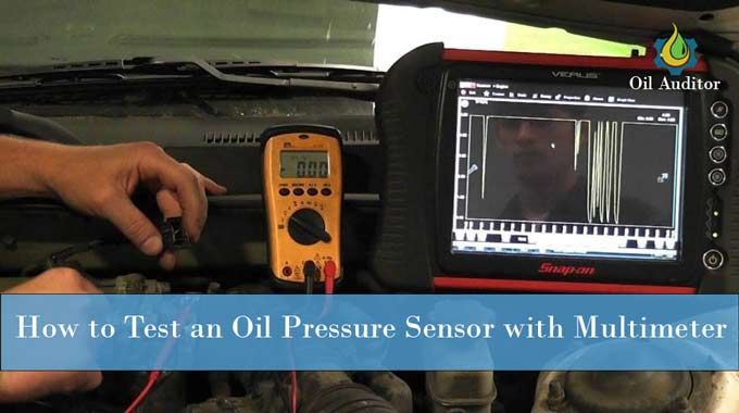
Do not use the disappearance of the warning light as the only proof that the repair is correct. A circuit can appear to work while having a weak terminal connection that fails later. Where available, a scan tool can also help confirm the sensor or switch status reported by the vehicle’s control system.
Source: i.ytimg.com
Electrical test passes
The repaired circuit meets the continuity, voltage, resistance, or isolation requirements specified for the vehicle.
Connector is secure
The connector locks into place and the terminals do not back out when the harness is handled normally.
Harness is protected
The repaired wiring is routed and retained so it does not contact heat sources, moving components, or sharp edges.
Warning behavior is normal
The oil pressure warning system follows the normal ignition-on and engine-running behavior specified for the vehicle.
What If the Oil Pressure Warning Stays On?
Stop and reassess the problem instead of repeatedly replacing wires or sensors. First confirm that the oil level is correct and that the engine does not have a genuine low-pressure condition. Actual low oil pressure can cause severe engine damage if the vehicle continues to run.
If oil pressure is known to be normal, return to the electrical diagnosis. Recheck the sensor, connector terminals, wiring continuity, shorts to ground, control-module inputs, and relevant diagnostic trouble codes according to the vehicle-specific service procedure.
Actual low oil pressure
A mechanical oil pressure problem must be diagnosed before treating the warning as an electrical issue.
Failed sensor or switch
The wiring can be correct while the pressure-sensing component itself has failed.
Connector problem
Loose, corroded, damaged, or incorrectly positioned terminals can interrupt the circuit.
Control-system fault
If the wiring and sensor test correctly, the vehicle may require further diagnosis of the control module, instrument system, or communication network.
Common Mistakes When Replacing Oil Pressure Sensor Wiring
Most wiring problems become harder to diagnose when the repair is performed before the circuit is identified. Cutting wires based only on appearance can introduce incorrect connections and make the original fault more difficult to locate.
Another common mistake is repairing the electrical connection without correcting the reason the wire failed. If the harness was rubbing against a bracket or exposed to excessive heat, the replacement wire can suffer the same damage unless the routing or protection is corrected.
Source: i.ytimg.com
Replacing the sensor without testing the wiring
A new sensor cannot correct an open, shorted, damaged, or poorly connected circuit.
Using the wrong wire size
The replacement wire should be suitable for the circuit and the vehicle’s operating environment.
Ignoring connector damage
A good wire connected to a loose or corroded terminal can still produce an intermittent fault.
Routing the wire incorrectly
A repair can fail again if the replacement section touches the exhaust, moving parts, or sharp edges.
Testing a connected circuit incorrectly
Continuity and resistance measurements can be misleading if other components remain connected when the service procedure requires circuit isolation.
Ignoring actual oil pressure
An oil pressure warning can represent a real engine lubrication problem, so electrical repair should not substitute for a mechanical pressure check when indicated.
When Professional Diagnosis Is the Better Choice
Professional help is appropriate when the wiring disappears into a difficult harness, multiple control modules are involved, the vehicle requires a scan tool for circuit diagnosis, or the correct terminal configuration cannot be established from reliable service information.
Stop DIY troubleshooting if the oil pressure warning remains on with the engine running and actual oil pressure has not been confirmed. A qualified technician can perform a mechanical oil pressure test and determine whether the problem is electrical or mechanical.
Complex electronic systems
Modern vehicles can route sensor information through multiple modules and communication networks, making a basic wire test insufficient.
No reliable wiring information
Do not guess connector terminals when the correct service information is unavailable.
Possible engine damage
A persistent oil pressure warning with abnormal engine operation requires prompt professional diagnosis.
Oil Pressure Sensor Wiring Repair Checklist
Use this checklist after completing the repair. It helps separate a completed wiring repair from a repair that only appears successful because the warning temporarily disappeared.
The final result should satisfy both the electrical test requirements and the vehicle’s normal operating behavior. If either part fails, continue diagnosis instead of assuming the wiring repair is complete.
Source: i.ytimg.com
Confirm the original fault
Identify the open circuit, short, damaged wire, failed terminal, or damaged connector before making the repair.
Replace or repair only the damaged wiring or connector as permitted by the service procedure.
Protect the repair
Restore appropriate routing, retention, insulation, sealing, and heat protection.
Perform final electrical tests
Confirm that the repaired circuit passes the required continuity, voltage, resistance, and short-circuit checks.
Verify warning-system operation
Confirm that the oil pressure warning system behaves normally and investigate any persistent warning before continuing to drive.
Repair or Replace: Which Is Better?
A small, localized wire fault may be suitable for an approved harness repair. A connector with damaged terminals may require a replacement terminal or pigtail. Extensive harness damage may make replacement of the affected harness section more appropriate.
The deciding factor is not simply how easy the repair looks. The repair must restore the circuit’s electrical integrity and provide adequate mechanical and environmental protection for its location.
Repair
Best suited to an isolated, accessible wiring fault when an approved repair method is available.
Replace a pigtail
Useful when the connector housing or terminal is damaged but the main harness remains serviceable.
Replace a harness section
May be preferable when damage is extensive, repeated, difficult to isolate, or located where a splice would not be appropriate.
Frequently Asked Questions
Q
Can I replace oil pressure sensor wiring myself?
Yes, a localized wiring repair can be a reasonable DIY task if you can identify the correct circuit and use an appropriate automotive wiring repair method. The difficulty increases when the circuit passes through multiple connectors or control modules.
Use vehicle-specific service information rather than assuming that every oil pressure circuit works the same way.
Q
How do I know if the oil pressure sensor wire is bad?
Visual damage can reveal a broken conductor, melted insulation, corrosion, or a damaged connector. Electrical testing can identify an open circuit or an unwanted connection to ground or another circuit.
A wiring fault should be confirmed with the vehicle’s specified test procedure before replacing the sensor.
Q
Can a bad oil pressure sensor wire cause the warning light to stay on?
Yes. An open, shorted, grounded, or poorly connected sensor circuit can cause the monitoring system to receive an incorrect signal. The exact result depends on the vehicle’s circuit design.
Because actual low oil pressure can create the same warning, do not assume that wiring is the cause without proper diagnosis.
Q
Can I just splice the broken oil pressure sensor wire?
A localized wire break may be repairable with an appropriate automotive-grade splice method, provided the vehicle’s repair procedure allows it. The splice must provide a secure electrical connection and adequate environmental and mechanical protection.
Simply twisting the wires together and covering them with ordinary electrical tape is not a reliable harness repair.
Q
What should I do if the oil pressure light stays on after replacing the wiring?
Do not continue driving until you determine whether the warning represents actual low oil pressure. Check the oil level and follow the vehicle’s procedure for confirming oil pressure.
If mechanical oil pressure is normal, continue electrical diagnosis of the sensor, connector, harness, control module, and related diagnostic codes.
Q
Does every oil pressure sensor use the same wiring?
No. Some vehicles use a simple pressure switch circuit, while others use electronic pressure sensors with different signal and power arrangements. Connector shapes, terminal positions, voltage requirements, and control-module connections also vary.
Always use wiring information for the exact vehicle, engine, model year, and market.
✦ Wrapping Up
Conclusion
Knowing how to replace oil pressure sensor wiring is mainly a matter of accurate diagnosis and careful harness repair. Start by confirming the fault, identify the correct circuit from vehicle-specific service information, and inspect the sensor, connector, terminals, and wiring before cutting anything.
After repairing the damaged wire or connector, retest the circuit and verify normal oil pressure warning behavior. If the warning remains on, treat the situation as an unresolved fault rather than assuming the wiring repair failed or replacing additional parts without testing.
💡 Key Takeaway
Before replacing oil pressure sensor wiring, identify the exact circuit and test it; after the repair, verify both electrical integrity and actual engine oil pressure when the warning persists.
Ethan Brooks is an automotive writer at Auto News 7, covering car news, vehicle maintenance, new model updates, recalls, and practical buying guides. He focuses on clear, useful information that helps drivers understand their vehicles and make better ownership decisions.
Learn how to ground oil pressure sensor circuits safely, identify the correct ground path, test continuity and voltage, and avoid common wiring mistakes.
Learn how to reset oil pressure sensor warnings safely, distinguish pressure faults from oil-life reminders, and know when diagnosis or repair is required.
Learn why bypassing an oil pressure sensor is risky, how the circuit works, and how to test low oil pressure safely without disabling engine protection.
Learn how to clean oil pressure sensor screen deposits, remove the sensor safely, inspect the filter screen, and avoid damage or false oil pressure readings.