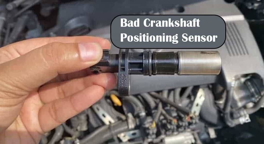
A crankshaft sensor may keep failing because of heat, wiring damage, contamination, incorrect sensor clearance, or a damaged reluctor wheel.
If you keep replacing the crankshaft position sensor in a U.S. vehicle and the problem returns, the sensor itself may not be the real cause. The crankshaft position sensor, often called the CKP sensor, works as part of a complete circuit that includes the sensor, wiring, connector, trigger wheel, engine control module, and mounting position.
Repeated failures can result from excessive heat, oil or coolant contamination, damaged wiring, loose terminals, vibration, physical damage, incorrect air gap, or a damaged reluctor wheel. A replacement sensor can appear to fix the vehicle temporarily while the underlying problem remains.
The most useful approach is to diagnose the entire CKP system before installing another sensor. Checking the stored fault codes, connector, harness, sensor mounting, trigger wheel, and signal can help determine whether the sensor is actually failing or simply reporting a problem elsewhere.
Source: mechlesson.com
Why Does My Crankshaft Sensor Keep Going Bad?
The most common explanation is that something is repeatedly damaging the sensor or interfering with its signal. Heat, electrical problems, fluid contamination, mechanical damage, incorrect sensor clearance, and a damaged reluctor wheel can all create recurring crankshaft sensor symptoms.
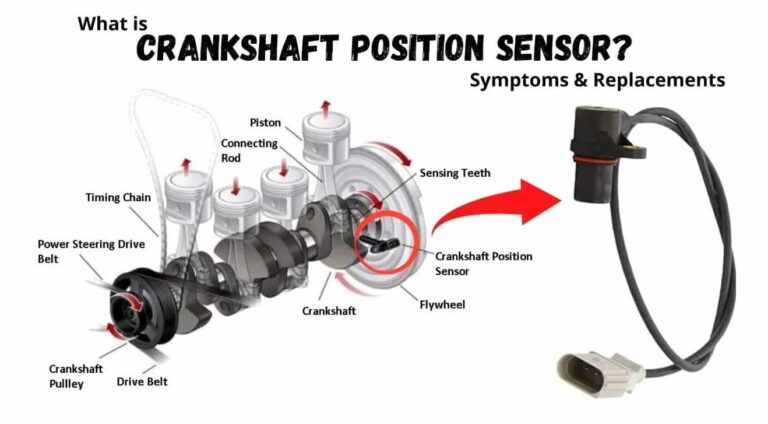
A crankshaft position sensor tells the engine control module where the crankshaft is and how fast it is turning. The computer uses that information for functions such as fuel injection and ignition timing. If the signal becomes unreliable, the engine may stall, become difficult to start, or fail to start.
If a new sensor works for a short time and then the same problem returns, avoid assuming that another sensor will solve it permanently. The repeated failure is a reason to inspect the complete circuit and the mechanical components that generate the sensor signal.
Source: trade.ra-grasse.de
Excessive heat
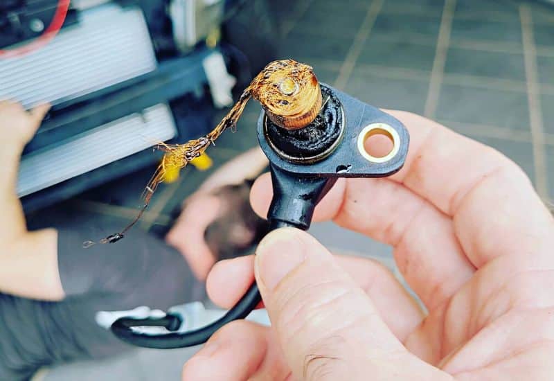
Repeated exposure to high engine temperatures can damage sensor electronics, internal windings, insulation, or surrounding wiring.
Wiring damage
Broken, chafed, melted, stretched, or shorted wiring can create the same symptoms as a failed sensor.
Fluid contamination
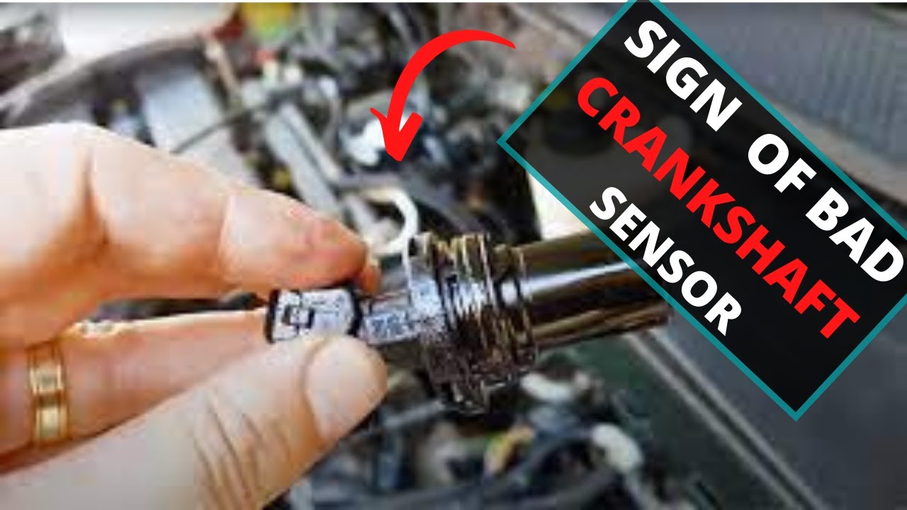
Engine oil, coolant, water, or other contaminants can affect the sensor, connector, terminals, or wiring.
Incorrect air gap
The distance between the sensor and reluctor must be correct for the specific engine. An incorrect gap can weaken or distort the signal.
Damaged reluctor wheel
Broken, bent, loose, cracked, or incorrectly positioned trigger-wheel components can produce an abnormal CKP signal even when the sensor is new.
What Does a Crankshaft Position Sensor Do?
The crankshaft position sensor monitors crankshaft movement and sends a signal to the engine control module. The module uses this information to determine engine speed and crankshaft position.
Depending on the vehicle design, the sensor may detect a reluctor, tone wheel, trigger wheel, or similar pattern attached to the crankshaft or another crank-driven component. The changing pattern creates the signal that the control module interprets.
Some vehicles use inductive or variable-reluctance sensors, while others use Hall-effect sensors or similar active designs. Because the electrical characteristics differ, a testing method that is correct for one sensor type may be inappropriate for another.
That difference matters when diagnosing repeated failures. Do not apply a generic resistance specification or testing procedure without checking the service information for the exact year, make, model, engine, and sensor.
Source: hitchesguide.com
Engine speed reference
The CKP signal helps the control module determine how quickly the crankshaft is rotating.
Crankshaft position reference
The signal helps the control module identify crankshaft position during engine operation.
Fuel and ignition control
The crankshaft signal contributes to decisions involving fuel injection and ignition timing.
Starting information
A usable CKP signal is important during cranking because the control module needs engine-speed and position information to manage engine startup.
Heat Can Make a Crankshaft Sensor Fail Repeatedly
Heat is a common reason a crankshaft sensor can work when the engine is cold but fail after the vehicle warms up. The sensor operates close to hot engine components, and repeated heating and cooling can stress its internal materials and electrical connections.
A heat-related failure can be especially confusing because the sensor may test normally during a cold inspection. Once the engine reaches operating temperature, an internal electrical fault or signal dropout may appear.
The same heat can also damage the wiring harness. Insulation may become brittle or softened, while repeated engine movement can cause already-weakened wires to break internally. A harness can therefore look acceptable from the outside while producing an intermittent electrical problem.
If the engine loses the CKP signal only when hot, reproduce the fault safely and test the system while the problem is occurring. Comparing cold and hot measurements can be more useful than replacing another sensor without testing.
Source: mechanicsdiary.com
Hot no-start
The engine starts when cold but cranks without starting after it has been driven and warmed up.
Heat-related stalling
The engine runs normally at first and then stalls after reaching operating temperature.
Intermittent signal loss
The CKP signal disappears temporarily and returns after the sensor or surrounding components cool down.
Damaged Wiring Can Make a Good Sensor Look Bad
A crankshaft sensor cannot send a reliable signal if its wiring or connector is damaged. This is one of the most important checks when a replacement sensor repeatedly develops the same fault.
Inspect the harness from the sensor toward the engine control module. Look for melted insulation, chafing, stretched wires, broken retaining clips, oil-soaked sections, corrosion, and areas where the harness can contact moving or hot components.
The connector deserves close attention as well. Bent, pushed-back, loose, corroded, or contaminated terminals can create intermittent electrical contact. A connector may appear plugged in while a terminal inside it fails to make reliable contact.
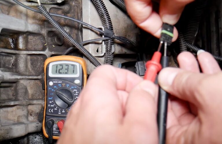
Do not rely only on a simple continuity test. A wire can show continuity when stationary but fail when the harness moves or when engine heat changes its condition. A voltage-drop or signal test performed according to the vehicle’s service procedure can provide more useful evidence.
Source: motorriderz.com
Chafed wiring
Harness insulation can wear through when wiring rubs against brackets, engine components, or other surfaces.
Melted insulation
Wiring routed too close to exhaust or other hot components can suffer heat damage.
Corroded terminals
Moisture or contamination can increase electrical resistance and interfere with the CKP signal.
Loose terminals
Poor terminal tension can cause intermittent signal loss even when the connector appears properly installed.
Oil, Coolant, Water, and Metal Debris Can Cause Problems
Contamination can interfere with crankshaft sensor operation, especially when a sensor is installed in an area exposed to engine fluids or road debris. Oil or coolant around the sensor and connector can indicate a separate leak that needs attention.
Metal debris can also matter. Magnetic crankshaft sensors can attract fine ferrous particles. Excessive contamination around the sensing area can interfere with the signal generated as the reluctor passes the sensor.
Water entering a connector can cause corrosion or intermittent electrical faults. This may be more likely after a damaged connector seal, fluid leak, pressure washing, or other event that allows moisture into the electrical connection.
If contamination is present, replacing only the sensor may provide a temporary improvement. The source of the contamination and the condition of the connector and harness should also be addressed.
Source: hitchesguide.com
Oil contamination
Oil around the sensor or connector can point to a leak and may affect electrical connections or sensor materials.
Coolant contamination
Coolant near the sensor or connector can indicate a leak that should be repaired before replacing parts repeatedly.
Water intrusion
Moisture inside electrical connectors can cause corrosion and intermittent circuit problems.
Metal particles
Ferrous debris can collect around some magnetic sensor designs and interfere with signal quality.
The Sensor Air Gap and Reluctor Wheel May Be the Real Problem
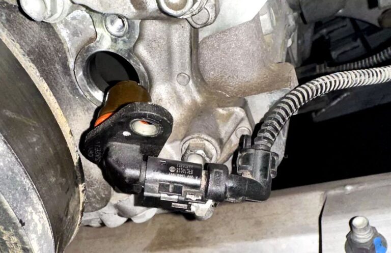
The crankshaft sensor must be positioned correctly in relation to the reluctor or trigger wheel. The required clearance varies by vehicle, so there is no universal crankshaft sensor gap that applies to every engine.
If the sensor is too far from the trigger wheel, the signal can become weak. If it is installed incorrectly or sits too close, the sensor may be vulnerable to physical contact or damage. A damaged mounting bracket can also change the intended position.
The reluctor itself can cause recurring faults. Broken teeth, cracks, excessive movement, incorrect indexing, or other mechanical damage can create an abnormal signal. In that situation, installing multiple new sensors will not correct the underlying problem.
Some engines use a fixed sensor mounting arrangement, while others have a specified adjustment procedure. Always follow the exact service information instead of setting the clearance based on a generic measurement.
Source: hitchesguide.com
Incorrect clearance
An air gap outside the manufacturer’s specification can produce a weak or distorted signal.
Damaged trigger wheel
A broken or damaged reluctor can create missing or irregular signal patterns.
Loose mechanical components
A trigger wheel or related component that moves from its intended position can alter the CKP signal.
Damaged mounting
A bent bracket or damaged sensor mounting point can prevent the sensor from maintaining the correct position.
Why a New Sensor May Fail Again After Installation
If the replacement sensor is installed with an incorrect clearance, exposed to the same excessive heat, connected to damaged wiring, or positioned near a defective reluctor, the original problem remains. The replacement part may then appear to have failed even though the installation did not correct the root cause.
A new sensor should therefore be treated as part of a repair process, not as the entire diagnosis. Verify the cause of the original fault before assuming that the component itself was defective.
Same electrical fault remains
Damaged wiring or a poor connector can continue to disrupt every replacement sensor.
Same heat exposure remains
A replacement sensor can suffer the same thermal stress if the underlying routing or heat source is unchanged.
Mechanical fault remains
A damaged reluctor or incorrect mounting position can continue to produce a bad signal.
How to Diagnose a Crankshaft Sensor That Keeps Failing
The best diagnosis moves from basic inspection to electrical and signal testing. Start with the vehicle’s diagnostic trouble codes and service information, then inspect the physical components before condemning the sensor.
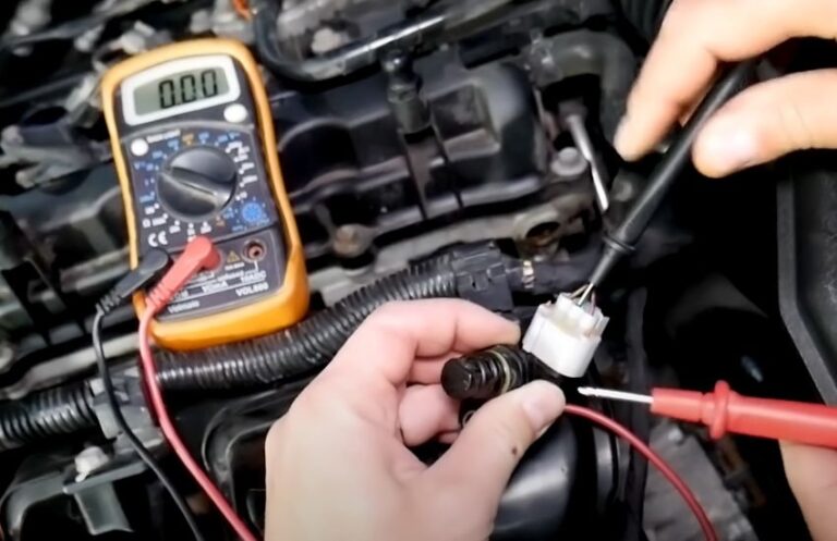
The exact testing method depends on the sensor design. Some crankshaft sensors are passive inductive sensors, while others contain active electronics. Because of this difference, do not use a generic resistance test unless the vehicle manufacturer specifies it.
Source: hitchesguide.com
1. Scan for diagnostic trouble codes
Record the stored and pending codes and note whether the code indicates a circuit, range, performance, or intermittent problem.
2. Inspect the sensor and connector
Look for cracks, impact damage, oil, coolant, water, corrosion, loose terminals, and other visible problems.
3. Inspect the harness
Check for chafing, melted insulation, stretched wires, poor routing, and contact with moving or hot components.
4. Check mounting and clearance
Verify the sensor installation and air gap against the exact vehicle specification.
5. Inspect the reluctor or trigger wheel
Look for damaged teeth, looseness, cracks, abnormal movement, or other mechanical problems when the design allows inspection.
6. Test power and ground when applicable
For an active sensor, verify the required supply and ground circuits according to the wiring diagram and service procedure.
7. Test the actual signal
Use the appropriate meter or oscilloscope procedure for the sensor type and compare the result with the manufacturer’s specifications.
8. Test when the fault occurs
If the problem happens only when hot, during cranking, or when the harness moves, reproduce that condition safely during diagnosis.
Why a Resistance Test Is Not Always Enough
A resistance reading can be useful for certain passive sensor designs when the manufacturer provides a resistance specification. However, a normal resistance reading does not prove that the sensor produces the correct signal during engine operation.
For active sensors, an ohmmeter resistance test may be inappropriate because the sensor contains electronic circuitry. Follow the manufacturer’s diagnostic procedure instead.
Static versus dynamic testing
Resistance measures an electrical property at rest, while a waveform test evaluates the signal generated as the engine turns.
Intermittent faults
A sensor or wire can pass a stationary test and still fail when exposed to heat, vibration, or engine movement.
How to Tell Whether the Sensor or Wiring Is Bad
The most useful clue is where the CKP signal disappears. If the sensor produces the correct signal but that signal does not reach the engine control module, the harness or connector becomes a stronger suspect. If power and ground are correct for an active sensor but its output is missing, the sensor, air gap, reluctor, or signal circuit needs closer testing.
A scan tool can also provide useful information. If engine speed remains at zero while the engine is cranking, the control module may not be receiving a usable crankshaft speed signal. That observation does not identify the failed component by itself, so it should be combined with circuit and signal testing.
For difficult intermittent faults, an oscilloscope can show signal dropouts, irregular pulses, noise, incorrect amplitude, or timing changes that a basic multimeter may not reveal.
Source: detroitchinatown.org
Signal missing directly at the sensor
Investigate the sensor, sensor power and ground when applicable, air gap, mounting, and reluctor.
Signal good at sensor but absent at module
Investigate the wiring, connectors, terminals, and circuit between the sensor and control module.
Signal fails only when hot
Investigate heat-sensitive sensor, connector, and harness faults while the engine is at the temperature where the problem occurs.
Signal is irregular at one crank position
Investigate the reluctor, trigger wheel, mechanical timing, and sensor clearance.
Common Mistakes When Replacing a Crankshaft Sensor
Repeatedly replacing the sensor without finding the cause can waste money and leave the vehicle vulnerable to another failure. A diagnostic trouble code should be treated as evidence about the system, not automatic proof that a particular part needs replacement.
Another common mistake is using a generic test value. Crankshaft sensor designs differ substantially, so resistance, voltage, clearance, and signal specifications must come from the correct service information.
It is also easy to overlook the battery and starting system. An inductive sensor can produce a different output during slow cranking, while low vehicle voltage can affect electronic control systems. If cranking speed or battery voltage is abnormal, diagnose that condition as part of the larger problem.
Source: hitchesguide.com
Replacing the sensor based only on a fault code
The code may identify a CKP circuit or signal problem without proving that the sensor itself is defective.
Using a universal resistance value
Sensor specifications vary by design and vehicle, so a generic resistance range can lead to an incorrect diagnosis.
Ignoring the connector
A loose, corroded, or damaged terminal can create recurring symptoms after a new sensor is installed.
Ignoring the reluctor
A damaged trigger wheel can continue to produce a bad signal with every new sensor.
Testing only when cold
A heat-sensitive fault may disappear during a cold inspection and return once the engine warms up.
Using an incorrect installation procedure
Incorrect mounting, clearance, fastener handling, or connector routing can cause repeat problems.
When Should You Stop Driving and Get Professional Help?
A crankshaft sensor problem can cause unexpected engine stalling or a no-start condition. If the vehicle repeatedly stalls while driving, loses power in traffic, or becomes unreliable at starting, continued driving can create a safety risk.
Professional diagnosis is especially appropriate when the fault is intermittent, occurs only when the engine is hot, requires waveform testing, involves difficult-to-access wiring, or appears to involve the reluctor or engine timing components.
Avoid probing electrical circuits or moving engine components unless you have the correct equipment and procedure. Keep hands, clothing, and test leads away from belts, pulleys, fans, and other moving components while the engine is running.
If the sensor is located near hot exhaust components or other high-temperature areas, allow components to cool when the repair procedure requires access. Follow the vehicle manufacturer’s repair instructions for disconnecting electrical components and performing tests.
Source: trade.ra-grasse.de
Repeated stalling
An engine that can shut off unexpectedly should be diagnosed promptly rather than repeatedly reset or restarted.
Persistent no-start
A vehicle that repeatedly cranks without starting needs a complete diagnosis rather than repeated sensor replacement.
Intermittent electrical faults
Intermittent faults can require specialized equipment and testing while the failure is active.
Mechanical trigger-wheel concerns
Reluctor or timing-related faults can require procedures beyond a basic sensor replacement.
Frequently Asked Questions
Q
Why does my crankshaft sensor keep failing after replacement?
A replacement sensor can fail again when the original cause remains. Common possibilities include excessive heat, damaged wiring, poor connector contact, fluid contamination, incorrect sensor clearance, physical damage, or a defective reluctor wheel.
The next repair should focus on identifying the underlying cause instead of simply installing another sensor.
Q
Can bad wiring cause a crankshaft sensor code?
Yes. Open circuits, short circuits, damaged insulation, corroded terminals, and loose connector contacts can prevent the engine control module from receiving a valid crankshaft signal.
Inspect and test the wiring and connector before concluding that the sensor itself has failed.
Q
Can overheating cause a crankshaft position sensor to fail?
Yes. Repeated exposure to high temperatures and thermal cycling can damage sensor components or nearby wiring. Some heat-related failures appear only after the engine reaches operating temperature.
If the problem occurs after warming up, test the CKP system while the fault is present when this can be done safely.
Q
Can oil cause a crankshaft sensor to go bad?
Oil contamination can contribute to sensor or connector problems, depending on the sensor design and where the leak occurs. Oil around a crankshaft sensor should also prompt an inspection for the source of the leak.
Replacing the sensor without correcting the contamination source can allow the problem to return.
Q
Does a bad crankshaft sensor always cause a check engine light?
Not necessarily. A control module may store a fault code when it detects an abnormal CKP signal, but the exact warning-light behavior depends on the vehicle and failure conditions.
Symptoms such as stalling, difficult starting, or a no-start condition should therefore be considered along with scan data and physical testing.
Q
Can a bad crankshaft sensor cause a car not to start?
Yes. If the engine control module cannot obtain a usable crankshaft speed or position signal, starting can become difficult or impossible on some vehicles.
However, a no-start condition has many possible causes, so the CKP system should be tested rather than assuming the sensor is responsible.
Q
Should I replace the crankshaft sensor again if the same code returns?
Not before checking why the code returned. Inspect the wiring, connector, mounting, sensor clearance, reluctor, power and ground circuits where applicable, and the actual CKP signal.
If the same fault returns after replacement, the recurrence itself is a strong reason to investigate the surrounding system.
✦ Wrapping Up
Conclusion
If you keep asking, why does my crankshaft sensor keep going bad, the answer is often found outside the sensor itself. Heat, damaged wiring, contaminated connectors, incorrect clearance, metal debris, and a damaged reluctor can all interfere with the crankshaft signal and make a replacement sensor appear to fail.
The most reliable approach is to diagnose the CKP system as a whole. Start with the diagnostic codes and visual inspection, then check the wiring and connector, confirm mounting and clearance, inspect the trigger wheel where accessible, and test the actual signal using the correct procedure for the sensor type.
If the engine stalls unexpectedly, the fault appears only when hot, or testing points toward a wiring or mechanical problem, professional diagnosis can prevent repeated parts replacement and help identify the actual cause.
💡 Key Takeaway
Before installing another crankshaft sensor, inspect the connector and harness, verify the sensor clearance and reluctor condition, and test the CKP signal according to the exact vehicle service procedure.
Ethan Brooks is an automotive writer at Auto News 7, covering car news, vehicle maintenance, new model updates, recalls, and practical buying guides. He focuses on clear, useful information that helps drivers understand their vehicles and make better ownership decisions.
Learn how to replace camshaft position sensor PT Cruiser models with this detailed step-by-step guide. Find symptoms, tools needed, replacement steps, troubleshooting tips, and common mistakes to avoid.
Learn how to replace a crankshaft position sensor with a detailed step-by-step guide, tools list, troubleshooting tips, safety advice, and signs of a successful repair.
Learn how to test camshaft position sensor wiring with a multimeter. Follow a safe step-by-step process to check power, ground, signal circuits, and common wiring faults.