To test camshaft position sensor wiring, verify power, ground, and signal circuits with a multimeter and compare readings to the vehicle manufacturer’s specifications.
Across the United States, camshaft position sensor problems are a common cause of engine performance issues, hard starting, misfires, and check engine lights. Before replacing the sensor, it is important to confirm that the wiring harness and electrical circuits are working correctly.
Understanding how to test camshaft position sensor wiring can help you identify damaged wires, poor grounds, voltage drops, loose connectors, or failed signal circuits. A systematic test process often reveals whether the fault is in the wiring, the sensor itself, or the engine control module.
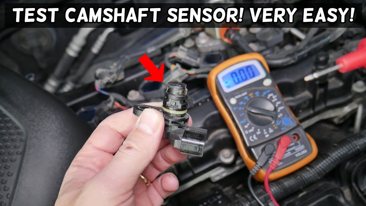
Source: youtube.com
What Is Camshaft Position Sensor Wiring?
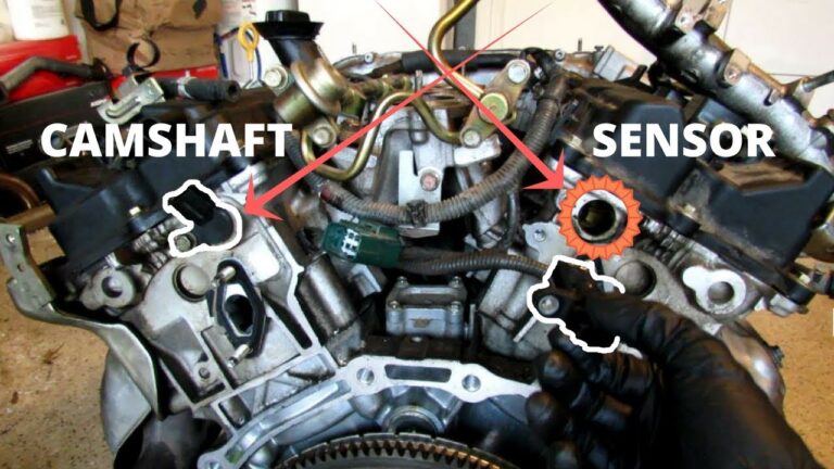
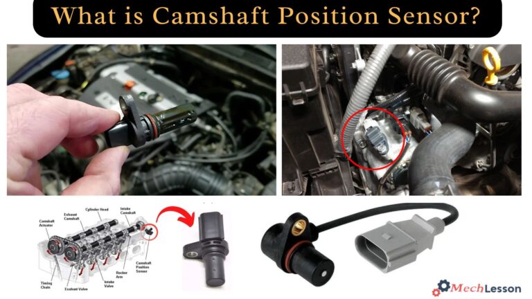
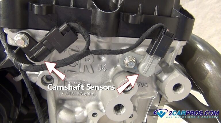
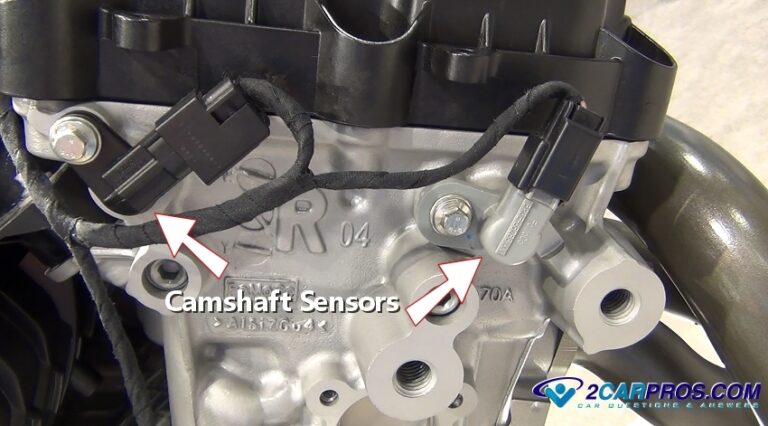
Camshaft position sensor wiring connects the sensor to the engine control module. The circuit allows the computer to monitor camshaft position and synchronize fuel injection and ignition timing.
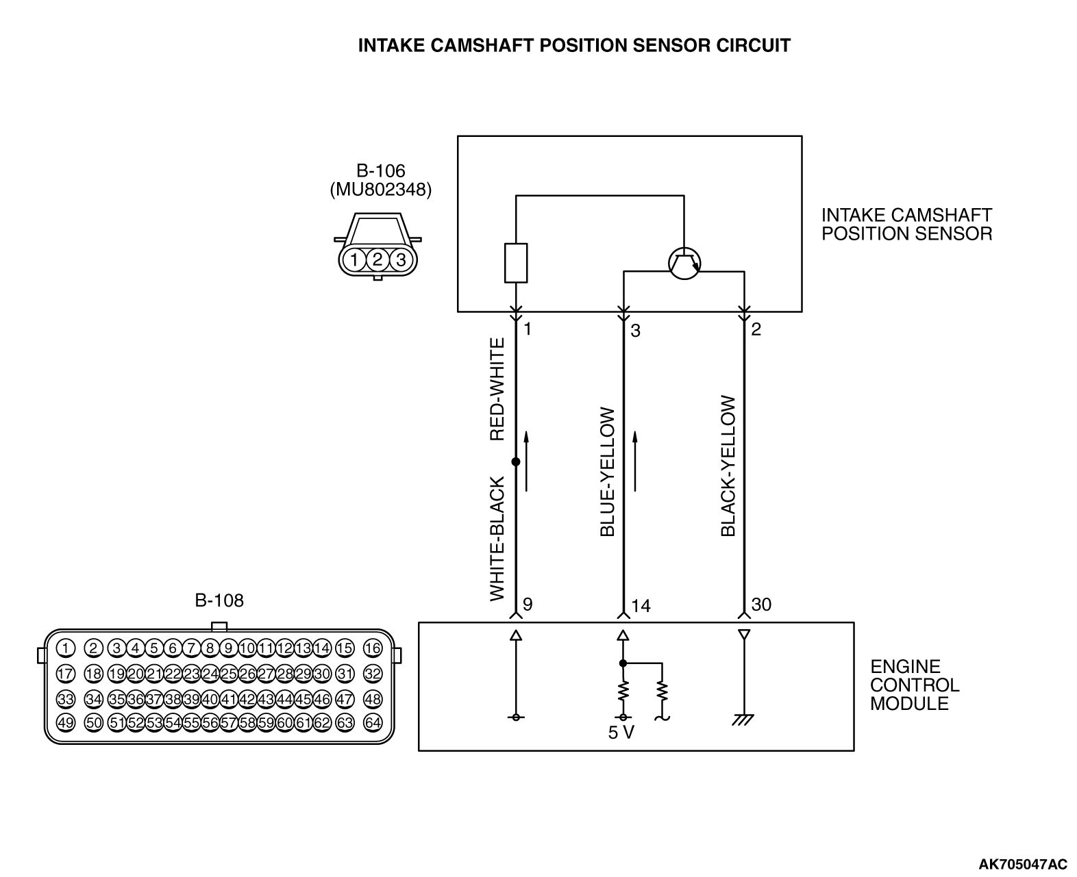
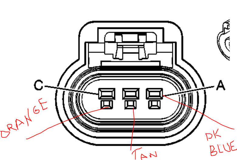
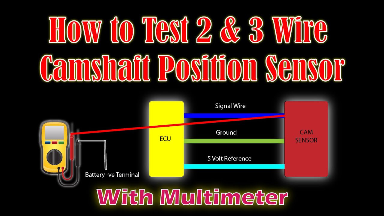
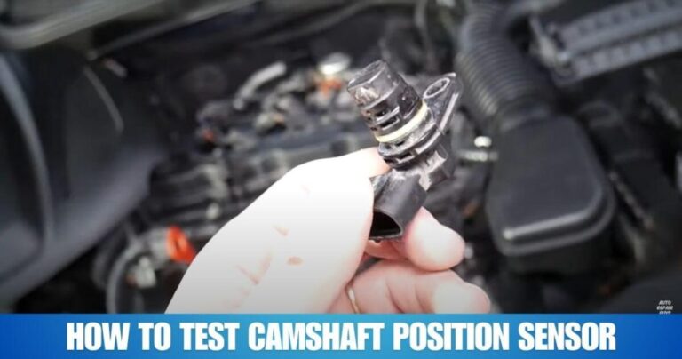
Most modern systems use either a two-wire magnetic sensor or a three-wire Hall-effect sensor. The wiring typically includes a power supply, ground, and signal wire.
Source: hitchesguide.com
Power Circuit
Supplies voltage to the sensor, often 5 volts or battery voltage depending on design.
Ground Circuit
Provides the electrical return path required for accurate sensor operation.
Signal Circuit
Carries the sensor output back to the engine control module.
Common Symptoms of Wiring Problems
A damaged sensor circuit may cause hard starting, rough running, stalling, poor acceleration, or diagnostic trouble codes related to camshaft position.
Check Engine Light
Frequently appears when the control module detects an abnormal sensor signal.
Tools and Safety Requirements
Gather the correct tools before beginning the diagnostic process. Using proper equipment improves accuracy and reduces the risk of damaging electrical components.
Always work with the vehicle parked on a level surface and follow manufacturer safety procedures.
Source: autopartswd.com
Digital Multimeter
Used to measure voltage, resistance, and continuity.
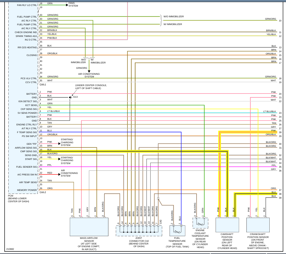
Wiring Diagram
Helps identify wire colors and circuit functions.
Back-Probe Pins
Allow testing without damaging connectors.
Safety Tips
Avoid piercing insulation when possible. Disconnect the battery when performing resistance or continuity checks on disconnected circuits.
Protect Electronics
Never apply external voltage to sensor circuits.
How to Test Camshaft Position Sensor Wiring Step by Step
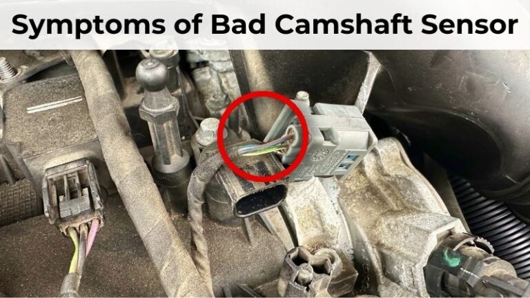
Start with a visual inspection. Look for melted insulation, loose connectors, corrosion, oil contamination, bent terminals, or damaged harness sections.
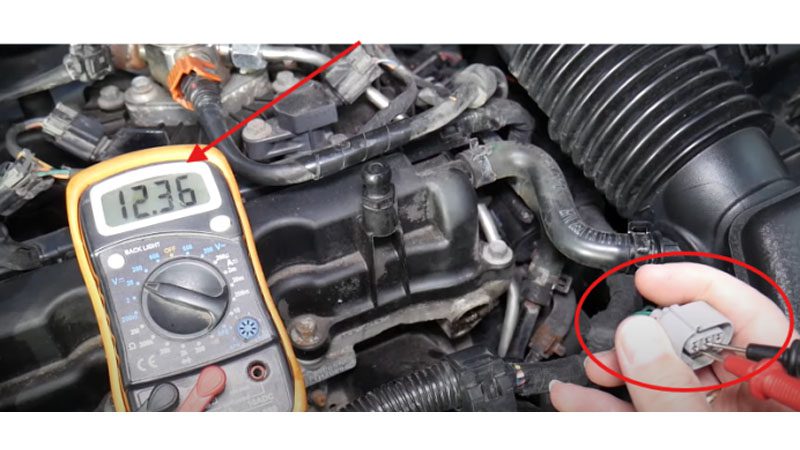
Turn the ignition key to the ON position without starting the engine. Measure reference voltage at the connector. A three-wire Hall-effect sensor commonly receives approximately 5 volts from the engine control module.
Next, test the ground circuit. Connect the multimeter between battery positive and the sensor ground terminal. A proper ground should show battery voltage during this test.
Finally, check the signal wire. Depending on the sensor design, the signal may switch between low and high voltage while the engine is cranking.
Source: hitchesguide.com
Step 1
Inspect wiring and connectors.
Step 2
Verify power supply voltage.
Step 3
Confirm ground integrity.
Step 4
Check signal circuit operation.
Signs of Success
A healthy circuit will show correct voltage supply, a solid ground connection, and a changing signal when the engine rotates.
Stable Readings
Consistent measurements indicate the wiring is likely functioning properly.
Testing Continuity and Voltage Drop
If voltage and ground checks appear normal, perform continuity testing with the circuit disconnected. This helps locate broken wires hidden inside the harness.
A voltage drop test under load is often more useful than a simple continuity test. Excessive voltage drop can indicate corrosion, loose terminals, or partially damaged conductors.
Source: storage.googleapis.com
Continuity Test
Checks whether electrical current can travel through the wire.
Voltage Drop Test
Measures resistance-related losses while the circuit operates.
When Results Are Abnormal
Repair or replace damaged wiring, connectors, or terminals before condemning the sensor itself.
Harness Repair
Use automotive-grade wiring and weather-resistant connections.
Common Mistakes and Troubleshooting Tips
One common mistake is replacing the sensor before testing the circuit. Many camshaft sensor trouble codes originate from wiring faults rather than failed sensors.
Another mistake is checking resistance on a powered circuit. This can damage the meter and produce inaccurate results.
If wiring tests correctly but the signal remains absent, inspect the sensor, reluctor wheel, timing components, and engine control module according to manufacturer procedures.
Source: fity.club
Do Not Guess
Confirm faults with measurements before replacing parts.
Use Specifications
Compare readings to manufacturer data whenever available.
When Professional Help Is Needed
Advanced diagnostics involving oscilloscopes, network communication faults, or control module testing may require a qualified automotive technician.
Complex Electrical Faults
Professional testing can save time when multiple systems are involved.
Quick Diagnostic Reference Table
This simple reference can help identify likely causes based on your test results.
Source: fity.club
No Power
Check blown fuses, damaged wiring, or control module supply issues.
Poor Ground
Inspect ground points, corrosion, and connector terminals.
No Signal
Test the sensor, wiring continuity, and camshaft trigger components.
Intermittent Signal
Look for loose connections, vibration damage, or heat-related failures.
Next Diagnostic Step
Record all measurements before replacing components. Accurate test data helps prevent unnecessary repairs.
Document Results
Write down voltage and continuity readings for comparison.
Frequently Asked Questions
Q
Can a bad wire cause a camshaft position sensor code?
Yes. Open circuits, short circuits, corrosion, and poor connections can trigger the same trouble codes as a failed sensor.
Q
How many wires does a camshaft position sensor have?
Many Hall-effect sensors have three wires for power, ground, and signal. Some magnetic sensors use only two wires.
Q
Can I test a camshaft sensor with a multimeter?
Yes. A multimeter can verify voltage supply, ground quality, continuity, and basic signal behavior. Some advanced tests require an oscilloscope.
Q
What voltage should a camshaft position sensor receive?
The exact value depends on vehicle design. Many Hall-effect sensors receive approximately 5 volts, while some systems use battery voltage.
Q
What should I do if the wiring tests good?
If the wiring passes all checks, continue testing the sensor itself, the trigger wheel, timing components, and the engine control module.
✦ Wrapping Up
Conclusion
Learning how to test camshaft position sensor wiring allows you to diagnose many engine performance problems without replacing parts unnecessarily. The key steps are checking power, ground, signal operation, continuity, and voltage drop.
A methodical testing process can quickly separate wiring faults from sensor failures and help restore proper engine operation.
💡 Key Takeaway
Start with a visual inspection, verify voltage and ground circuits, then test signal integrity before replacing the camshaft position sensor.
Ethan Brooks is an automotive writer at Auto News 7, covering car news, vehicle maintenance, new model updates, recalls, and practical buying guides. He focuses on clear, useful information that helps drivers understand their vehicles and make better ownership decisions.
Learn how to fix a camshaft position sensor with step-by-step troubleshooting, testing, replacement instructions, common symptoms, costs, and repair tips.
Learn how to test a camshaft position sensor on Ford vehicles using a multimeter and scan tool. Follow a clear step-by-step process to diagnose sensor faults, wiring issues, and engine performance problems.
Learn how to replace intake camshaft position sensor with a detailed step-by-step guide, tools list, troubleshooting tips, safety advice, and common mistakes to avoid.