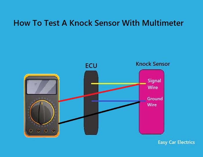
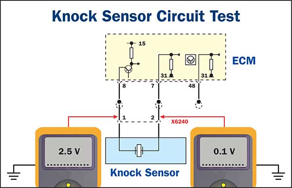
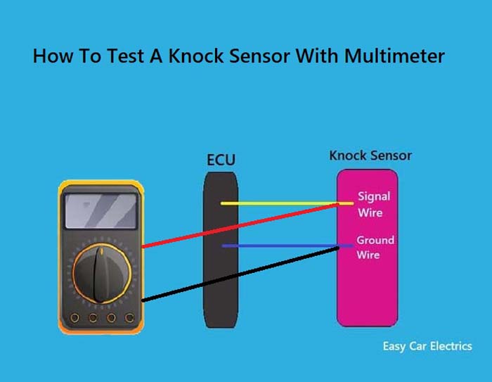
Test knock sensor wiring by checking connector condition, wire continuity, shorts to ground or power, and the correct ECM pin connections.
If you are diagnosing a knock sensor problem on a vehicle in the United States, the safest starting point is the vehicle-specific factory wiring diagram and service information. Knock sensor circuits vary by engine, model year, and manufacturer. Some systems use a single signal circuit, while others use two signal wires, a ground circuit, or shielded wiring.
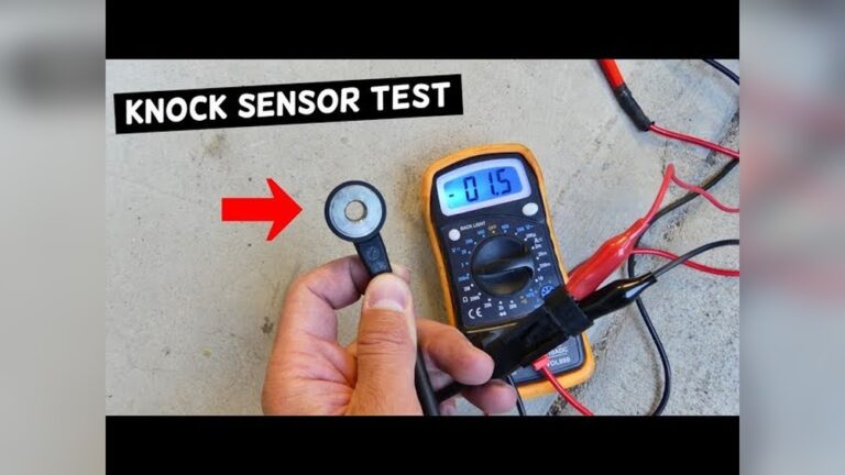
To test knock sensor wiring, switch the ignition off, disconnect the sensor and ECM or PCM connectors as required by the service procedure, and use a digital multimeter to check continuity between the sensor connector and the correct control-module terminals. Then check that the circuit is not unintentionally shorted to ground, battery power, or another circuit. Do not assume a generic resistance value applies to every knock sensor.
Source: youtube.com
What Does Knock Sensor Wiring Do?
A knock sensor detects vibration associated with engine knock or detonation and sends an electrical signal to the engine control module. The control module uses that information as part of its strategy for managing ignition timing and engine operation.
The wiring provides the electrical path between the sensor and the engine control module. Depending on the design, the circuit may contain one or more signal wires, a ground connection, and shielding intended to reduce electrical interference.
A wiring problem can therefore produce symptoms that resemble a bad sensor. Open circuits, shorts, corrosion, damaged insulation, loose terminals, and poor connections can all interfere with the signal.
Source: wiringdiagram.2bitboer.com
Open circuit
A broken conductor or disconnected terminal prevents the expected electrical path between the knock sensor and control module.
Short to ground
A signal wire unintentionally contacts ground or a grounded part of the circuit, changing the expected electrical behavior.
Short to power
A signal circuit contacts a powered circuit, potentially producing an incorrect voltage or diagnostic fault.
Connector fault
Corrosion, backed-out terminals, damaged locks, or poor terminal tension can interrupt the circuit even when the wires look intact.
Why the Wiring Diagram Matters
Never identify knock sensor terminals by wire color alone. Manufacturers can use different terminal layouts and circuit strategies on different engines. The factory diagram identifies the sensor terminals, connector cavities, ECM or PCM pins, shield connections, and any relevant grounds.
A factory service procedure may also specify a particular resistance range for the sensor. For example, documented Mazda procedures use substantially different sensor resistance specifications on different engines, showing why a universal resistance number is unreliable.
Find the exact vehicle
Use the year, make, model, engine, and applicable engine-control system when locating the wiring diagram.
Identify both ends
Record the knock sensor connector terminals and the corresponding ECM or PCM terminals before connecting the meter.
Tools and Information You Need
You can perform a basic knock sensor wiring inspection with a digital multimeter, but the meter alone does not tell you which terminals to test. Start with the correct wiring diagram and service procedure for the vehicle.
A basic diagnostic setup should include a digital multimeter with resistance and continuity functions, suitable back-probing or test leads, the vehicle wiring diagram, and basic hand tools for accessing the connector. An OBD-II scan tool can also help identify stored diagnostic trouble codes and monitor relevant data when the vehicle supports it.
Disconnect the battery or follow the manufacturer’s prescribed procedure when required. Some vehicles require specific precautions before disconnecting the ECM, PCM, or other control-module connectors.
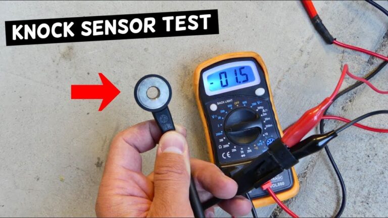
Source: youtube.com
Digital multimeter
Use a meter capable of measuring low resistance accurately and, where specified, high resistance in the megohm range.
Factory wiring information
Use it to identify sensor terminals, ECM or PCM pins, grounds, shields, and the required test conditions.
Test leads
Use suitable probes that will not spread, damage, or deform small connector terminals.
Scan tool
Use diagnostic trouble codes and available data as supporting evidence rather than treating a code as proof that the sensor or wiring is defective.
How to Test Knock Sensor Wiring Step by Step
The most useful wiring test is a controlled continuity and short-circuit check between the knock sensor connector and the ECM or PCM. Perform the checks with the circuit powered down and the connectors disconnected as required by the vehicle’s service procedure.
Do not probe an ECM connector randomly. A wrong connection can damage a control module or produce a misleading reading. Identify every test point from the wiring diagram before starting.
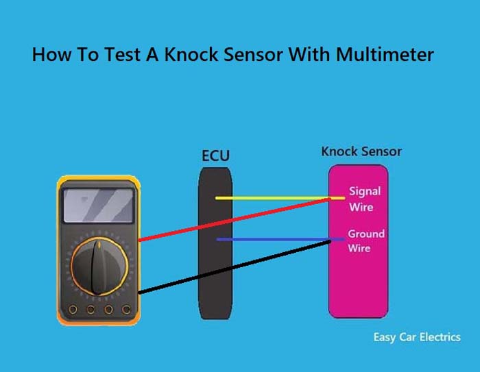
Source: youtube.com
Step 1: Read the diagnostic codes
Scan the vehicle and record the stored codes and freeze-frame information when available. Knock sensor-related codes can point toward a circuit, signal, or performance problem, but they do not by themselves identify the failed component.
Step 2: Switch the ignition off
Turn the ignition off and follow the manufacturer’s shutdown procedure. Disconnect the battery when the service information requires it.
Step 3: Inspect the sensor connector
Look for corrosion, moisture, damaged seals, broken locks, pushed-back terminals, loose terminal fit, and damaged wiring near the connector.
Step 4: Disconnect the required connectors
Disconnect the knock sensor connector and ECM or PCM connector when the factory procedure calls for an isolated harness test.
Step 5: Identify the circuit terminals
Use the wiring diagram to identify each knock sensor terminal and its matching ECM or PCM terminal.
Step 6: Check continuity
Set the multimeter to resistance or continuity and measure each wire from the sensor-side terminal to its specified control-module terminal. A properly functioning wire should show the continuity specified by the service information.
Step 7: Check for shorts to ground
With the connectors disconnected, test each relevant signal wire against ground according to the factory procedure. An unexpected low-resistance connection can indicate a short.
Step 8: Check for shorts to power
Check the relevant circuit against power circuits as specified by the wiring diagram. The expected result depends on the circuit design.
Step 9: Check for shorts between circuit wires
Where the service procedure calls for it, check that separate knock sensor circuits are not unintentionally connected to one another.
Step 10: Test the sensor separately
If the harness passes its wiring tests, measure the knock sensor itself using the exact resistance or signal specification for that vehicle.
How to Check Knock Sensor Wire Continuity
First, make sure both ends of the wire are electrically isolated according to the service procedure. Put the multimeter in resistance mode and place one probe on the correct sensor-side terminal and the other on the matching ECM or PCM terminal.
A very low resistance reading is commonly expected for an intact harness, but the exact acceptable value belongs to the vehicle manufacturer. One HELLA diagnostic procedure, for example, gives a wiring target of less than 1 ohm under its specified test conditions. That value should not be transferred to every vehicle without verification.
If the meter shows an open circuit or a substantially higher value than the specified limit, inspect the harness for a broken conductor, poor splice, damaged connector terminal, or corrosion.
Good result
The measured resistance falls within the vehicle-specific wiring specification.
Open result
The meter indicates no usable connection between the specified terminals, suggesting an open circuit or disconnected terminal.
High resistance
A reading above specification can indicate corrosion, a damaged conductor, poor terminal contact, or an unsuitable test connection.
How to Check for a Short to Ground
With the sensor and control-module connectors disconnected, test the relevant signal wire against ground as directed by the service information. The correct result is not necessarily the same for every circuit because some knock sensor systems intentionally use a grounded shield or other ground reference.
For example, a documented HELLA procedure calls for checking the wiring against ground and specifies at least 30 megohms for the relevant conductors, while noting that a shielding connection may intentionally have continuity to ground. This illustrates why the wiring diagram must be consulted before interpreting the meter.
Do not condemn a shield
A shield may intentionally connect to ground, so continuity to ground is not automatically a fault.
Test isolated circuits
Disconnect the components required by the service procedure so the meter does not measure another circuit through the control module or sensor.
How to Test the Knock Sensor After the Wiring Passes
If the wiring has correct continuity and no unintended shorts, test the knock sensor itself. The exact procedure depends on the sensor design and vehicle.
Some factory procedures specify resistance between sensor terminals. Others measure resistance between a sensor terminal and ground. The expected value can differ dramatically between engines. For example, documented service procedures include knock sensor specifications measured in kilohms, megohms, and low single-digit ohms on different applications.
That variation is why replacing a sensor solely because its resistance does not match a generic internet value can lead to an incorrect diagnosis.
Source: youtube.com
Follow the exact specification
Use the service manual for the specific engine, including its stated temperature and measurement points.
Check physical condition
Look for cracking, impact damage, contamination, or installation problems before deciding the sensor has failed.
Check installation requirements
Some knock sensors require a specific mounting condition or tightening torque for correct operation.
How to Find an Intermittent Knock Sensor Wiring Fault
An intermittent wiring fault can pass a stationary continuity test and still fail while the vehicle is moving or the engine is vibrating. If the circuit tests correctly but the fault returns, inspect the harness more closely rather than immediately replacing the sensor.
Pay particular attention to areas where the harness bends, contacts brackets, passes near hot components, or enters the connector. A conductor can break internally while the outer insulation remains intact.
A controlled wiggle test can sometimes expose an intermittent connection. With the circuit safely isolated and the meter connected according to the service procedure, gently move the harness while watching for an unexpected change. Do not pull hard on wires or disturb an energized circuit unless the manufacturer specifically provides a powered test.
Source: wiringtoday.com
Connector movement
Watch for changes caused by loose or poorly tensioned terminals when the harness is moved gently.
Harness damage
Inspect for chafing, heat damage, crushed sections, previous repairs, and stretched wiring.
Corrosion
Green or discolored terminals, moisture, and damaged seals can increase resistance or create intermittent connections.
Shielding problems
A damaged or incorrectly repaired shield can affect a sensitive sensor circuit, depending on the vehicle design.
What the Test Results Mean
Interpret the readings as a diagnostic sequence rather than as isolated numbers. A failed continuity test points toward the harness or its connections. A wiring harness that passes every specified test shifts attention toward the sensor, installation, control-module input, or another engine-management condition.
Factory diagnostic procedures commonly separate the checks into open-circuit testing, short-circuit testing, sensor testing, and related signal or data checks. Following that order helps prevent unnecessary parts replacement.
Source: wiringdiagram.2bitboer.com
No continuity between sensor and ECM
Suspect an open circuit, damaged terminal, broken wire, or connector problem. Repair the circuit and retest.
Continuity to ground where none should exist
Suspect a short to ground, damaged insulation, incorrect repair, or another wiring fault.
Continuity to power where none should exist
Suspect contact with a powered circuit or an incorrect harness repair.
Wiring passes but sensor test fails
Compare the sensor measurement with the exact manufacturer specification before replacing the sensor.
Wiring and sensor both pass
Continue with the vehicle-specific diagnostic procedure, which may include signal, control-module, grounding, or mechanical checks.
Common Mistakes When Testing Knock Sensor Wiring
The most common diagnostic mistake is treating all knock sensor circuits as if they use the same design. They do not. Service procedures from different vehicles demonstrate different connector arrangements, resistance specifications, grounding strategies, and control-module pin assignments.
Another common mistake is testing continuity with the control module still connected when the procedure calls for an isolated harness. The connected electronics can affect the measurement and can also create an avoidable risk of damage if the wrong terminals are probed.
Avoid using a generic resistance value found online as the final diagnostic test. The correct specification must come from information applicable to the exact vehicle and engine.
Source: wiringdigital.com
Using wire color alone
Wire colors can change between models and production configurations. Confirm terminal numbers with the wiring diagram.
Testing a powered circuit in resistance mode
Resistance measurements should be performed with the circuit in the condition specified by the manufacturer, normally with power removed.
Skipping connector inspection
A corroded or loose terminal can cause the same symptoms as a broken wire.
Replacing the sensor immediately
A knock sensor code does not automatically prove that the sensor itself has failed.
Ignoring the shield
Some circuits use shielded wiring, and the shield can have a deliberate connection to ground.
When to Stop Testing and Get Professional Help
Stop and obtain professional service information or diagnostic help if the ECM or PCM connector pinout is unclear, the circuit requires specialized equipment, or the test could expose a control module to an incorrect voltage. A modern engine-control system can contain sensitive electronics that are expensive to replace.
Professional diagnosis is also appropriate when the wiring and sensor tests pass but the vehicle continues to set a knock sensor fault. The remaining cause may require live-data analysis, oscilloscope testing, manufacturer-specific diagnostic software, or additional engine checks.
If the vehicle has severe engine knock, abnormal combustion, significant loss of power, or other serious drivability symptoms, avoid continued driving until the cause is identified. A knock sensor is part of an engine protection and control strategy, so an unresolved fault should not be dismissed simply because the engine still runs.
Source: storage.googleapis.com
Use specialist equipment when required
Some diagnostic procedures require an oscilloscope, breakout box, manufacturer scan tool, or other specialized equipment.
Protect the control module
Never apply battery voltage to an ECM or PCM terminal unless the manufacturer explicitly specifies that test.
Use qualified repair support
A qualified technician can interpret vehicle-specific wiring diagrams and perform advanced circuit and signal testing when basic checks do not locate the fault.
Frequently Asked Questions
Q
How do I test knock sensor wiring with a multimeter?
Disconnect the knock sensor and the control-module connectors as required by the vehicle service procedure. Use the wiring diagram to identify the correct terminals, then check continuity from each sensor circuit to its specified ECM or PCM terminal.
After checking continuity, test the relevant wires for unintended shorts to ground, battery power, and other circuits. Compare every reading with the vehicle-specific specification.
Q
What resistance should knock sensor wiring have?
There is no single resistance value that applies to every knock sensor harness. A wiring circuit normally needs to show continuity with resistance within the manufacturer’s specified limit, but the exact limit depends on the vehicle and circuit design.
For example, some documented procedures specify a wiring target below 1 ohm, while sensor resistance specifications on other vehicles range from low ohms to hundreds of kilohms or several megohms. Always use the specification for the exact application.
Q
Can bad knock sensor wiring cause a check engine light?
Yes. An open circuit, short, poor connector connection, or other wiring problem can prevent the engine control module from receiving the expected knock sensor signal. The module may then store a diagnostic trouble code and illuminate the malfunction indicator lamp, depending on the vehicle’s diagnostic strategy.
Q
How can I tell if a knock sensor wire is broken?
With the circuit isolated, test continuity between the sensor connector and the corresponding ECM or PCM terminal. If the circuit does not meet the specified continuity requirement, inspect the harness, connectors, terminals, splices, and areas exposed to heat or movement.
An intermittent break may require additional inspection or a controlled harness movement test performed according to the service procedure.
Q
Should a knock sensor wire have continuity to ground?
It depends on which wire you are testing. A signal wire may need to be electrically isolated from ground, while a dedicated ground or shield may intentionally connect to ground.
Check the wiring diagram before interpreting a ground reading. Treating every ground connection as a fault can lead to an incorrect diagnosis.
Q
Can I test a knock sensor without removing it?
Some basic electrical checks can be performed with the sensor installed, provided the connector can be accessed and the manufacturer specifies the test. However, certain sensor resistance or physical inspections may require the sensor to be disconnected or removed.
Follow the exact procedure for the vehicle rather than assuming that an installed sensor can be tested the same way on every engine.
Q
What should I do if the wiring tests good but the knock sensor code returns?
Continue with the vehicle-specific diagnostic procedure instead of replacing parts at random. Test the sensor itself against its specified electrical characteristics and inspect installation, grounding, connector condition, and available diagnostic data.
If those checks pass, advanced testing such as signal waveform analysis or control-module circuit testing may be necessary.
✦ Wrapping Up
Conclusion
Learning how to test knock sensor wiring starts with the wiring diagram, not the multimeter. Once the correct terminals are identified, isolate the circuit and check continuity from the knock sensor connector to the ECM or PCM. Then check for unintended shorts to ground, power, and other circuits.
If the harness passes, test the knock sensor using the exact specification for the vehicle. Because knock sensor designs and resistance values vary significantly between engines, generic numbers can produce a false diagnosis.
Careful connector inspection and vehicle-specific testing can help separate a wiring fault from a failed sensor. When the basic checks pass but the fault remains, use the manufacturer’s diagnostic procedure or seek qualified diagnostic assistance rather than guessing at replacement parts.
💡 Key Takeaway
Get the exact factory wiring diagram first, then test each knock sensor circuit for correct continuity and unwanted shorts before condemning the sensor or ECM.
Ethan Brooks is an automotive writer at Auto News 7, covering car news, vehicle maintenance, new model updates, recalls, and practical buying guides. He focuses on clear, useful information that helps drivers understand their vehicles and make better ownership decisions.