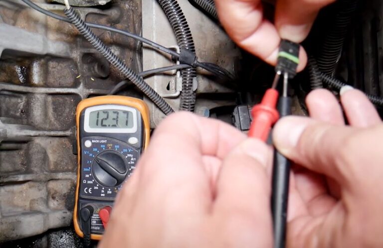
To check if a crankshaft sensor is bad, scan for trouble codes and cranking RPM, inspect its wiring and connector, identify the sensor type, and test its power, ground, resistance, or signal as specified for your vehicle. A missing or abnormal crankshaft signal with good wiring is much stronger evidence of sensor failure than symptoms alone.
For drivers in the United States, crankshaft position sensor problems are commonly diagnosed through the vehicle’s OBD-II system before parts are replaced. Most gasoline-powered light-duty vehicles sold in the U.S. since the 1996 model year use standardized OBD-II diagnostics, so an affordable scan tool can provide valuable information such as diagnostic trouble codes and, on many vehicles, engine RPM while the starter is cranking.
The crankshaft position sensor, usually abbreviated CKP, tells the engine control module how fast the crankshaft is turning and where it is in its rotation. The computer uses that information as a major reference for ignition and fuel-injection control. If the signal disappears or becomes unreliable, the engine may crank without starting, stall unexpectedly, become difficult to restart, run poorly, or illuminate the Check Engine light.
However, those symptoms do not prove the sensor itself has failed. A damaged connector, broken wire, poor ground, incorrect sensor air gap, damaged reluctor or tone wheel, low cranking speed, weak battery, or another engine-management fault can create similar symptoms. The most reliable approach is to diagnose the entire crankshaft position sensor circuit instead of replacing the sensor based only on a warning light or a no-start condition.
This guide explains how to check if crankshaft sensor is bad using a practical diagnostic sequence suitable for many U.S.-market cars, SUVs, and light trucks. Exact pin assignments, resistance ranges, supply voltages, air-gap specifications, and waveform requirements vary by vehicle, so manufacturer service information should always take priority over generic numbers.
Source: samarins.com
What Does a Crankshaft Position Sensor Do?
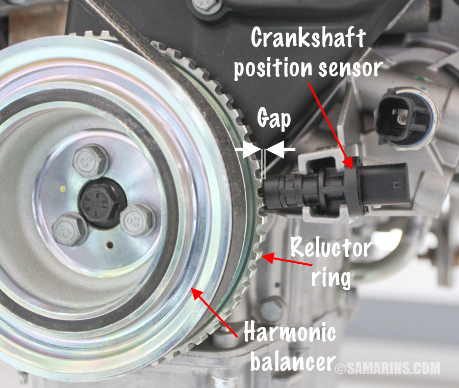
A crankshaft position sensor monitors crankshaft rotational speed and position. It reads a trigger wheel, tone wheel, reluctor ring, or similar target connected mechanically to the crankshaft. As the crankshaft rotates, the sensor produces an electrical signal that the powertrain control module or engine control module interprets.
That signal helps the computer determine engine RPM and crankshaft position. Depending on the engine-management system, the information is used with other inputs, including the camshaft position sensor, to control ignition timing, fuel injection, misfire monitoring, and synchronization.
The sensor may be mounted near the crankshaft pulley, behind or near the harmonic balancer, along the engine block, near the oil pan, or at the transmission bell housing where it can read a flywheel or flexplate-mounted target. Location varies substantially among engines.
Two sensor designs are especially important for diagnosis. A variable-reluctance or magnetic sensor is generally a passive sensor that generates its own alternating-current signal as the reluctor passes it. A Hall-effect sensor is an active electronic sensor that normally requires a power supply and ground and produces a switching signal. Because these designs operate differently, a test appropriate for one may be inappropriate for the other.
Source: mechlesson.com
Variable-reluctance sensor
Usually generates an AC waveform and may be tested for winding resistance and AC output when the manufacturer’s procedure allows it.
Hall-effect sensor
Normally requires power and ground and produces a digital switching signal that should be checked according to the wiring diagram.
Reluctor or tone wheel
Provides the physical target read by the sensor. A damaged, loose, contaminated, or incorrectly positioned target can create a bad signal even when the sensor itself works.
Symptoms to Check Before Testing the Crankshaft Sensor
Before connecting test equipment, note exactly how the vehicle behaves. A faulty CKP sensor can produce recognizable patterns, but none of these symptoms should be treated as a stand-alone diagnosis.
A complete signal loss may cause an engine to crank normally without starting because the engine computer cannot establish a usable crankshaft reference. An intermittent sensor or circuit fault may instead cause sudden stalling, a hot-engine restart problem, brief hesitation, or an engine that dies and then restarts after cooling.
Some vehicles may also experience misfire-like operation, rough running, reduced performance, or an illuminated Check Engine light. These symptoms overlap heavily with fuel-delivery, ignition, camshaft sensor, wiring, battery, charging, and mechanical timing problems.
Source: mycaremyway.co.uk
Engine cranks but does not start
A missing CKP signal is one possible cause, especially if scan data also shows no engine-speed signal while cranking.
Intermittent stalling
An electrical sensor fault may appear only after the engine compartment becomes hot or after vibration affects a damaged wire or terminal.
Hard starting
A weak or irregular crankshaft signal can interfere with synchronization, but battery condition and other starting-system issues should also be checked.
Check Engine light
Crankshaft position sensor circuit faults can store diagnostic trouble codes, although a code identifies the monitored problem rather than automatically proving the sensor itself has failed.
Tachometer or scan-data RPM behavior
Some vehicles may show no useful engine-speed information during a CKP failure. Scan-tool RPM is generally more useful diagnostically than relying on the dashboard tachometer.
Common Crankshaft Position Sensor Trouble Codes
Generic OBD-II crankshaft position sensor circuit codes include members of the P0335 through P0339 family. Depending on the code and vehicle, the computer may be detecting an electrical circuit fault, an implausible signal, an intermittent condition, or another crankshaft position signal problem.
Do not interpret a code such as P0335 as an automatic instruction to install a new sensor. The circuit includes the sensor, connector, wiring, electrical supply or reference where applicable, ground, target wheel, and control-module input. Diagnosis should determine which part of that system is actually responsible.
How to Check If Crankshaft Sensor Is Bad Step by Step
The most efficient diagnosis starts with information that can be collected without disconnecting components. Scan the vehicle, observe cranking RPM, inspect the circuit, identify the sensor design, and then perform the correct electrical test.
You may need an OBD-II scan tool, digital multimeter, wiring diagram, back-probe leads, basic hand tools, and vehicle-specific service information. An oscilloscope is especially useful for evaluating signal quality but is not required for every preliminary check.
Work on a cool engine whenever access is near the exhaust system or other hot components. During any live cranking test, keep hands, clothing, meter leads, and tools away from belts, pulleys, fans, and other moving parts. Do not pierce insulation or short terminals simply to obtain a measurement.
Source: harleydavidsonblog.com
Step 1: Scan for diagnostic trouble codes
Connect an OBD-II scanner and record stored, pending, and permanent codes where available. Do not erase the codes before documenting them because freeze-frame or fault information may help identify the conditions under which the problem occurred.
Step 2: Watch engine RPM while cranking
Open live data and monitor engine speed while an assistant cranks the engine. A persistent 0 RPM reading can indicate that the control module is not receiving a usable crankshaft-speed signal, but it does not by itself prove the CKP sensor is defective.
Step 3: Locate and visually inspect the sensor
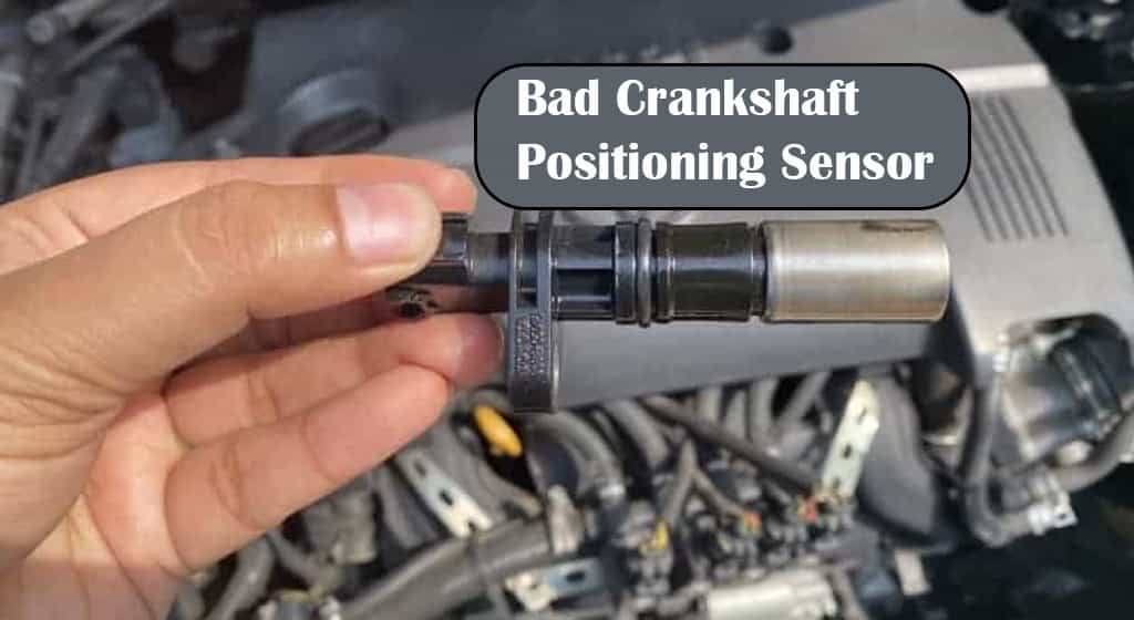
Check the sensor body, mounting position, connector, and nearby harness. Look for loose terminals, broken locking tabs, oil contamination, water intrusion, corrosion, melted insulation, chafing, pin damage, or wiring pulled tight against the engine.
Step 4: Identify the sensor type
Use a wiring diagram, repair manual, or reliable service information to determine whether the CKP sensor is variable-reluctance, Hall-effect, or another design. Do not assume its type based only on the number of wires.
Step 5: Perform the correct electrical checks
Test the circuits and signal using the procedure specified for that sensor type. Compare measurements with vehicle-specific specifications rather than a universal resistance or voltage number.
Step 6: Inspect the target and sensor air gap when applicable
A damaged reluctor wheel, excessive air gap, debris on a magnetic sensor, or mechanical movement of the target can disrupt the signal and imitate a failed sensor.
Step 7: Confirm the diagnosis before replacement
If wiring integrity, power, ground, target condition, and mechanical operation are correct but the CKP signal is missing or clearly abnormal, the sensor is a much stronger candidate for replacement.
What Does 0 RPM During Cranking Mean?
If the starter turns the engine but scan data remains at 0 RPM, the engine control module may not be recognizing the crankshaft position signal. This is a useful clue because it directly relates to a function provided by the CKP circuit.
Still, check the complete circuit. A broken signal wire, missing Hall-sensor supply voltage, bad ground, damaged trigger wheel, excessive sensor gap, connector problem, or control-module issue can also result in no detected RPM. Verify that the engine is actually rotating at normal cranking speed before drawing a conclusion.
How to Test an Inductive Crankshaft Sensor With a Multimeter
A variable-reluctance crankshaft sensor normally contains a coil and magnet and produces an AC signal when the target passes the sensor. If service information confirms that your vehicle uses this sensor design, resistance and AC-output checks can help determine whether the sensor is functional.
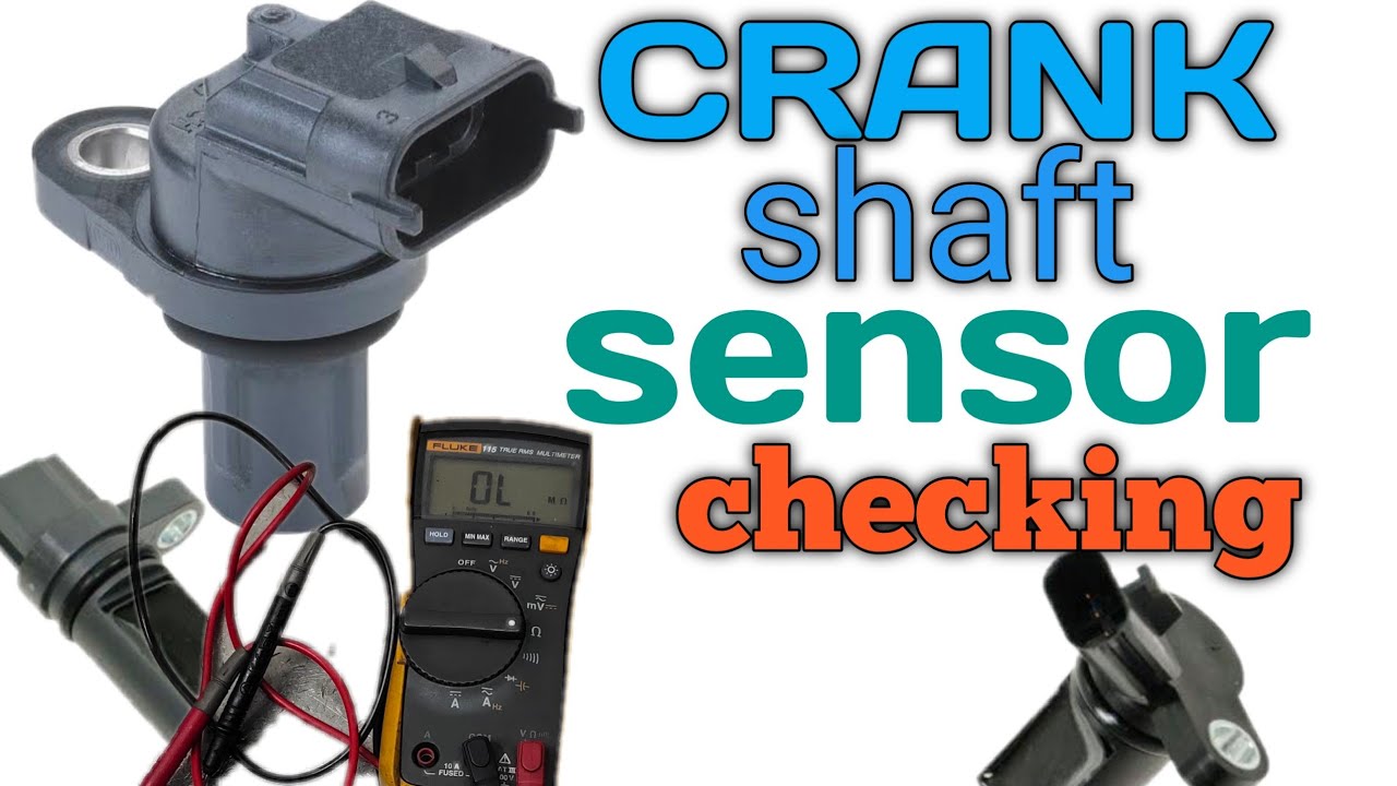
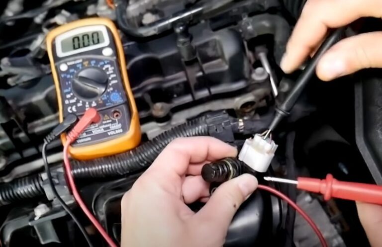
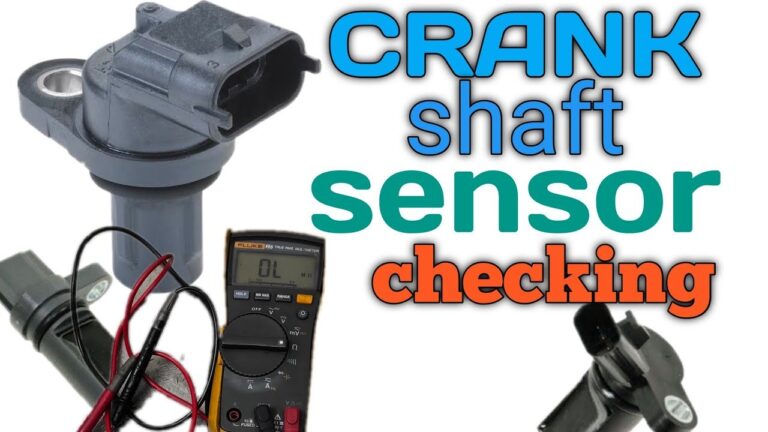
For a resistance test, switch the ignition off and disconnect the sensor as directed by the service procedure. Set the digital multimeter to resistance and measure across the designated sensor terminals. Compare the result with the manufacturer’s specification.
Do not rely on a universal resistance number. Some automotive references show inductive CKP sensors within ranges of several hundred to around one thousand ohms, while actual specifications vary substantially by application. The correct value is the one published for your engine and sensor.
An open circuit or a reading dramatically outside the specified range can indicate a damaged winding. A very low reading may indicate an internal short, depending on the specified design. A normal resistance reading, however, does not prove that the sensor produces a correct signal under operating conditions.
A dynamic test provides more information. Where the manufacturer permits it, set the meter to a low AC-voltage range and measure the sensor output while the engine is cranking. An inductive sensor should generate an AC signal as the reluctor teeth pass it. Output varies with cranking speed, sensor design, air gap, and meter, so compare the measurement with service information.
If the resistance is correct but output is weak or absent, investigate the sensor gap, metal debris, reluctor condition, cranking speed, wiring, and measurement setup before declaring the sensor defective.
Source: storage.googleapis.com
Open circuit
May indicate a broken internal winding or an open connection if the manufacturer’s specification calls for measurable resistance.
Resistance outside specification
Can indicate internal sensor damage, but always compare with the exact vehicle specification.
No AC output while cranking
Can indicate a failed sensor, but excessive air gap, a damaged reluctor, incorrect meter setup, or insufficient target movement must also be considered.
Normal resistance
Confirms only part of the sensor’s electrical condition and does not guarantee that its dynamic waveform is correct.
How to Test a Hall-Effect Crankshaft Position Sensor
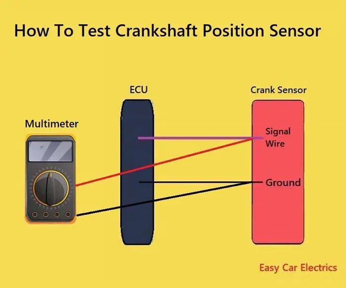
A Hall-effect CKP sensor should be approached differently because it contains active electronics. Instead of beginning with a resistance measurement across the sensor, use the wiring diagram to identify its supply, ground, and signal circuits.
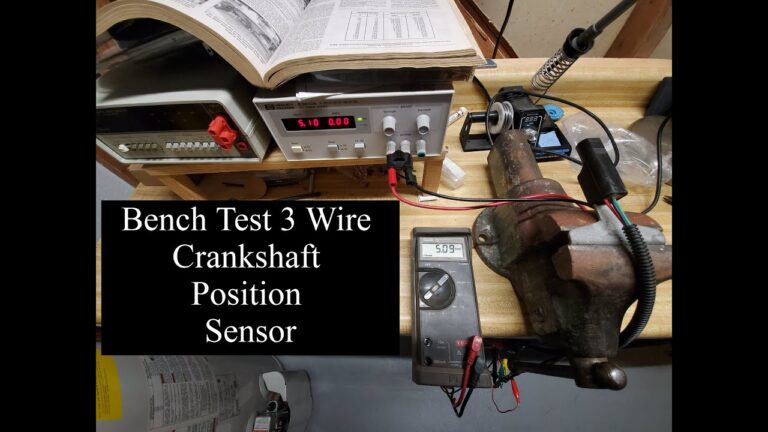
With the circuit powered according to the service procedure, verify that the sensor receives the specified supply voltage. Many automotive Hall-effect sensors operate from a regulated reference supply, but not every vehicle uses the same voltage. Never assume that a particular wire must carry 5 volts based only on a generic diagram.
Next, verify the sensor ground. A circuit can show continuity with the ignition off and still have excessive resistance under load. Where the manufacturer’s procedure permits it, a voltage-drop test while the circuit is operating can expose a weak terminal, damaged wire, or poor ground connection.
Finally, evaluate the signal while the crankshaft rotates. A functioning Hall-effect sensor typically switches its signal between defined voltage states as the target passes. A digital multimeter may show a changing or averaged voltage, but it cannot display the waveform as clearly as an oscilloscope.
If supply voltage and ground are correct but the signal remains fixed when it should be switching, investigate the signal wire, connector terminals, target wheel, sensor air gap, and sensor itself. If those supporting components are verified, an internally failed sensor becomes more likely.
Avoid measuring resistance directly across an unidentified active sensor. Some diagnostic equipment applies voltage during resistance testing, and using an inappropriate test on an electronic sensor can produce misleading results or potentially damage sensitive electronics.
Source: motorriderz.com
Check supply voltage
Confirm the actual specification and correct terminal from the vehicle wiring diagram.
Check sensor ground
Verify that the ground circuit can carry current without excessive voltage drop when the prescribed procedure allows it.
Check signal switching
Monitor the signal while cranking or rotating the engine as specified. A scope provides more diagnostic detail than a standard meter.
Do not guess terminal functions
Connecting a meter or jumper to the wrong terminal can lead to a false diagnosis or electrical damage.
How to Tell If the Sensor, Wiring, or Reluctor Is Actually Bad
The strongest crankshaft sensor diagnosis comes from separating the sensor from the rest of the circuit. A trouble code or missing signal tells you where to investigate, not automatically which component to replace.
If a Hall sensor lacks its required supply voltage, replacing the sensor may accomplish nothing. Trace the reference or power circuit according to the wiring diagram. Likewise, a good sensor cannot communicate through an open or shorted signal wire.
Inspect terminals carefully. A connector may appear fully seated while a spread, backed-out, corroded, or oil-contaminated terminal creates intermittent contact. Harness faults often appear where wiring bends sharply, passes near hot exhaust components, or rubs against brackets.
The mechanical target deserves attention as well. Broken or damaged reluctor teeth, a loose tone ring, excessive runout, debris, or an incorrect sensor-to-target gap can alter the signal. Certain problems may only become obvious when viewing the waveform with an oscilloscope.
A useful diagnostic pattern is to verify power and ground first for an active sensor, confirm wiring continuity and isolation as specified, verify the target is moving correctly, and then evaluate the actual CKP signal. A failed signal with all supporting conditions correct gives far more confidence than replacing a sensor because the engine stalled once.
Source: storage.googleapis.com
Bad sensor more likely
Correct power and ground are present, wiring is intact, the target is mechanically sound, but the expected sensor signal is absent or repeatedly fails under the same conditions.
Wiring fault more likely
Measurements change when the harness moves, terminals are damaged, continuity is lost, or a wire is shorted to power, ground, or another circuit.
Reluctor problem more likely
The signal contains repeatable irregularities associated with target damage, excessive gap, runout, contamination, or a displaced tone wheel.
Further diagnosis needed
The CKP signal appears normal but the engine still will not start or continues to stall. Fuel, ignition, camshaft synchronization, mechanical timing, battery voltage, and other systems may need testing.
Why an Oscilloscope Is Better for Intermittent CKP Problems
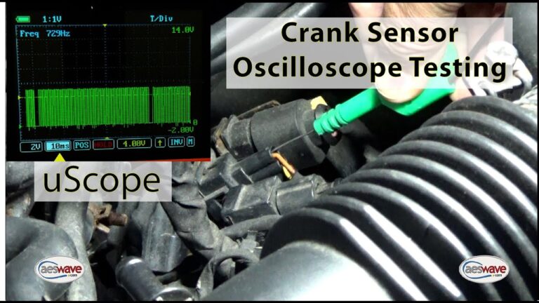
A digital multimeter reduces rapidly changing electrical activity to a numerical reading. That makes it useful for basic voltage, resistance, and supply checks but less effective for identifying momentary signal dropouts or abnormal waveform shapes.
An oscilloscope displays the signal over time. A technician can inspect amplitude, consistency, missing reference features, electrical noise, dropouts, and changes that occur as engine speed or temperature changes. Scope testing is particularly valuable when the vehicle stalls intermittently but passes basic static tests.
Crankshaft Sensor Test Results and What to Do Next
Use the overall pattern of evidence rather than one isolated number. The table below summarizes common findings and the logical next check.
A sensor should generally be replaced only after the test result is interpreted in the context of the wiring diagram, sensor design, mechanical target, and manufacturer specification. Doing so reduces unnecessary parts replacement and helps prevent a wiring or mechanical problem from being mistaken for a defective sensor.
Cranking RPM is 0 on scan data
Check CKP power and ground where applicable, connector condition, wiring, sensor output, target movement, and sensor gap.
Cranking RPM appears normal
The control module is receiving some engine-speed information. Continue diagnosing fuel, ignition, synchronization, mechanical timing, or other relevant systems if the engine will not start.
Inductive sensor resistance is outside specification
Recheck meter setup and terminals. If the reading remains outside the vehicle-specific specification, the sensor may have an internal winding fault.
Inductive sensor has resistance but no usable dynamic output
Inspect cranking speed, target condition, air gap, contamination, and measurement setup before replacing the sensor.
Hall sensor has no supply voltage
Diagnose the supply circuit, reference circuit, fuse or shared circuit as applicable before replacing the sensor.
Hall sensor has good power and ground but no switching signal
Check the signal circuit, target, connector, and gap. If those are correct, the sensor itself becomes a strong suspect.
Signal fails only when the engine becomes hot
Capture live data or waveform information during the failure. Heat-related sensor or wiring faults may disappear after the engine cools.
Signs That Your Diagnosis Was Successful
A successful diagnosis identifies why the crankshaft signal was missing or incorrect rather than merely making the symptom disappear temporarily. After the repair, clear codes when appropriate, start the engine, confirm normal operation, and rescan the vehicle.
If the original problem occurred only under specific conditions, such as a fully warmed engine, repeat those conditions carefully. Confirm that engine RPM is detected consistently and that the relevant fault code does not immediately return.
Common Mistakes When Checking a Crankshaft Sensor
Crankshaft sensor diagnosis is frequently complicated by testing the wrong circuit or assuming every sensor works the same way. Avoiding a few common mistakes can save considerable diagnostic time.
One of the biggest errors is replacing a CKP sensor because a crankshaft-related trouble code is present. Diagnostic codes identify a circuit or operating condition monitored by the computer. They do not necessarily identify the failed physical part.
Another mistake is using a generic resistance specification. Sensor designs and calibrations differ. A measurement that looks abnormal according to an online example could be completely normal for a different application.
Do not assume a new sensor eliminates the CKP circuit as a possibility. Incorrect parts, connector damage, harness faults, installation problems, excessive sensor gap, and mechanical target problems can remain after replacement.
Replacing the sensor from symptoms alone
Hard starts and stalling have many possible causes. Test the CKP circuit before buying parts.
Using an ohmmeter on an unidentified sensor
Confirm the sensor type and manufacturer procedure first, particularly when active Hall-effect electronics may be present.
Ignoring battery condition
A weak battery can reduce cranking speed and system voltage, potentially affecting diagnostic results and preventing normal starting for reasons unrelated to the CKP sensor.
Ignoring the reluctor
The sensor can only report what it reads. A damaged or displaced trigger wheel can create an abnormal signal even with a functional sensor.
Damaging wiring while back-probing
Use suitable test leads and approved access methods. Forcing oversized probes into terminals can spread them and create a new intermittent fault.
Testing only when the engine is cold
If the complaint occurs after warm-up, diagnostic testing may need to be performed safely under the same temperature conditions.
When to Stop DIY Testing and Get Professional Diagnosis
Basic scanning, visual inspection, and carefully performed meter checks are realistic DIY tasks for many vehicle owners. More complex diagnosis becomes appropriate when the sensor is difficult to reach, the required test involves sensitive control-module circuits, or basic results conflict with each other.
Professional diagnosis is especially useful when the vehicle stalls unpredictably in traffic, when the CKP waveform must be compared with the camshaft signal, when the reluctor is inside the engine or transmission, or when the wiring diagram requires testing circuits at the engine control module.
A repair shop with a capable scan tool and oscilloscope can monitor CKP and camshaft signals simultaneously and reproduce temperature-related or vibration-related failures. That can be more economical than replacing several components based on symptoms alone.
Seek help for unsafe access
Do not work around rotating or hot components if the sensor cannot be reached safely.
Seek help for intermittent stalls
A vehicle that can stall unexpectedly may be unsafe to drive until the cause is identified.
Seek help when basic tests disagree
Normal power, ground, resistance, and basic signal readings do not rule out waveform, synchronization, or mechanical problems.
Frequently Asked Questions About How to Check If Crankshaft Sensor Is Bad
Q
Can I tell if a crankshaft sensor is bad without a multimeter?
You can gather strong clues without a multimeter by scanning for trouble codes, checking live engine RPM during cranking, inspecting the connector and harness, and observing whether the problem is temperature-related. However, those checks may not distinguish a bad sensor from a wiring, power, ground, or reluctor problem.
Electrical testing or waveform analysis is usually needed when you want greater confidence before replacing the sensor.
Q
Will a bad crankshaft sensor always set a code?
No. Some failures can be intermittent, occur too briefly, or happen under conditions that do not immediately meet the control module’s criteria for storing a diagnostic trouble code. Pending codes and live data can therefore be useful even when the Check Engine light is not continuously illuminated.
Q
Can a bad crankshaft sensor cause a crank-no-start condition?
Yes. On many engine-management systems, losing the crankshaft position signal can prevent the computer from correctly controlling ignition and fuel injection. The starter may turn the engine normally while the engine fails to run.
A crank-no-start condition has many other causes, however, so confirm the CKP signal rather than assuming the sensor is responsible.
Q
What should crankshaft sensor resistance be?
There is no single resistance value that applies to every crankshaft position sensor. Some passive magnetic sensors have measurable winding resistance, but the correct specification depends on the exact sensor and vehicle.
Hall-effect and other active sensor designs should not automatically be diagnosed with a generic resistance test. Consult vehicle-specific service information before connecting an ohmmeter.
Q
Can a crankshaft sensor fail only when the engine is hot?
Yes. Internal electrical faults and wiring problems can become temperature-sensitive. A vehicle may start normally when cold, stall after reaching operating temperature, and restart after cooling.
When the problem is intermittent, capturing live RPM or the CKP waveform during the actual failure is more useful than testing the vehicle only after it has cooled.
Q
Does 0 RPM while cranking prove the crankshaft sensor is bad?
No. A 0 RPM reading during cranking is a valuable sign that the control module may not be receiving a usable crankshaft-speed signal, but the reason could be the sensor, wiring, connector, power supply, ground, reluctor, excessive air gap, or another circuit problem.
Use the 0 RPM result as the reason to test the CKP system, not as proof that the sensor itself must be replaced.
✦ Wrapping Up
Conclusion
Knowing how to check if crankshaft sensor is bad is mainly about proving whether the engine computer is receiving a correct crankshaft signal. Start with an OBD-II scan and cranking RPM, inspect the connector and wiring, identify the sensor type, and then perform the electrical test appropriate for that design.
For an inductive sensor, manufacturer-approved resistance and AC-output tests can reveal internal or signal problems. For a Hall-effect sensor, verify the specified power supply, ground, and switching signal instead of relying on a generic resistance check. In both cases, remember that the reluctor wheel, sensor gap, wiring, terminals, battery condition, and mechanical operation can affect the result.
If the sensor’s supporting circuits and mechanical target test correctly but its expected signal is absent or abnormal, replacement becomes a well-supported next step. If the basic measurements look normal and the problem remains, waveform testing and broader engine diagnosis are preferable to replacing additional parts by trial and error.
💡 Key Takeaway
Scan the vehicle first, check engine RPM while cranking, inspect the CKP circuit, identify the sensor design, and verify the correct signal before replacing the crankshaft position sensor.
Ethan Brooks is an automotive writer at Auto News 7, covering car news, vehicle maintenance, new model updates, recalls, and practical buying guides. He focuses on clear, useful information that helps drivers understand their vehicles and make better ownership decisions.