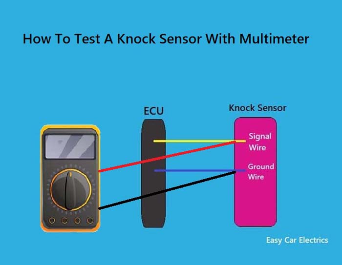
Most factory knock sensors are not manually calibrated; correct installation, testing, and ECU learning provide the proper calibration.
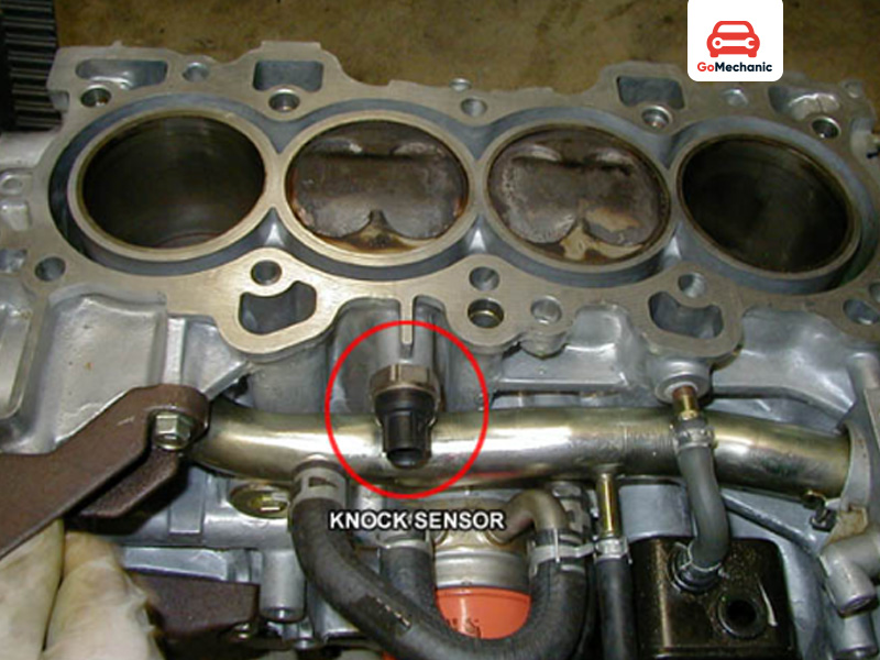
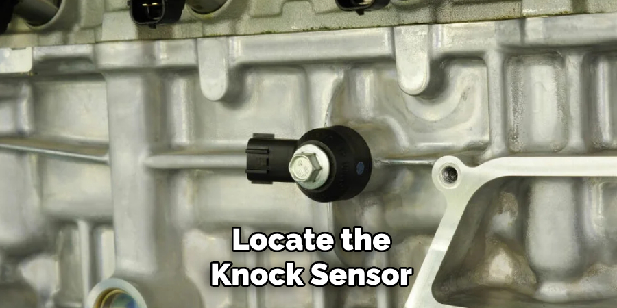
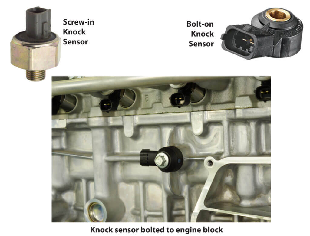
If you are working on a gasoline vehicle in the United States, the first thing to know about how to calibrate knock sensor systems is that calibration usually does not mean adjusting the sensor itself. A typical knock sensor is a piezoelectric device mounted to the engine block. It detects vibration associated with combustion knock and sends an electrical signal to the engine control module. The computer then uses that signal as part of its knock-control strategy.
For most factory vehicles sold in the U.S., there is no universal adjustment screw or manual calibration procedure. The correct process depends on the vehicle, engine, sensor design, and engine-control system. A service procedure may require checking resistance or capacitance, inspecting the wiring, cleaning the mounting surface, tightening the sensor to an exact torque, clearing diagnostic codes, or performing an ECU learning procedure. Aftermarket engine-management systems can require a separate calibration of sensor sensitivity, frequency filtering, or knock thresholds.
Source: qaqooking.wiki
What Does Knock Sensor Calibration Mean?
Knock sensor calibration means making sure the knock-detection system produces and interprets the expected signal under the conditions specified by the vehicle or ECU manufacturer. That can involve the physical sensor, its installation, the wiring, the engine computer, or a combination of these parts.
A typical knock sensor uses a piezoelectric element. Engine-block vibration creates mechanical stress in the element, which produces an electrical signal. The ECU analyzes that signal rather than simply treating every vibration as engine knock.
The word calibration can therefore describe different procedures. On a factory vehicle, it may mean restoring the sensor to its specified mechanical and electrical condition. On an aftermarket ECU, it may mean configuring the sensor’s signal characteristics and establishing appropriate knock-detection thresholds.
Source: safetyfic.com
Factory system
The sensor is generally a fixed-output component. The vehicle manufacturer defines the sensor specification and the ECU’s knock-control strategy.
Aftermarket ECU
The tuner may need to configure sensor type, frequency filtering, gain, thresholds, and other knock-control parameters.
Replacement sensor
Correct part selection, mounting surface preparation, connector condition, and specified torque can be more important than attempting to alter the sensor itself.
Why Knock Sensors Need Accurate Installation
A knock sensor responds to mechanical vibration, so its contact with the engine matters. A loose fastener, incorrect torque, contamination between the sensor and block, or an incorrect mounting arrangement can change the signal reaching the ECU.
There is no single torque value that applies to every vehicle. Published service procedures show that specifications vary substantially between applications. The correct specification must come from the exact vehicle or sensor documentation.
Mounting surface
Keep the specified sensor-to-block contact area clean and free of corrosion, dirt, grease, or unintended washers.
Fastener torque
Use a calibrated torque wrench and the exact specification for the application.
Before You Calibrate a Knock Sensor
Start with the vehicle identification and service information. Identify the engine, model year, engine-control system, and exact knock sensor. A procedure for one engine should not be transferred to another simply because both systems use a piezoelectric knock sensor.
Gather a digital multimeter and, when required by the service procedure, a capacitance meter, scan tool, wiring diagram, torque wrench, and the specified sensor socket or tool. For aftermarket ECU work, you may also need ECU tuning software and reliable information about the sensor’s frequency characteristics.
Disconnect the ignition system or battery only when the service procedure calls for it. Some vehicles have specific procedures for preserving learned data, resetting adaptations, or completing readiness checks after repairs.
Source: go.screenpal.com
Vehicle information
Confirm the exact year, engine, sensor part number, ECU, and applicable service procedure.
Electrical tools
Use a suitable multimeter and any additional measuring equipment required by the manufacturer’s test procedure.
Mechanical tools
Use a calibrated torque wrench and the correct tool for the sensor fastener.
Scan or tuning equipment
Use a compatible scan tool for factory diagnostics or the manufacturer’s software for an aftermarket ECU.
Safety Checks
Work on a cool engine when access to the sensor requires contact with hot engine components. Keep tools and wiring away from moving belts, fans, and pulleys. If the sensor is located under an intake manifold or other major component, follow the vehicle’s removal and installation procedure rather than forcing access.
Do not create an artificial engine-knock condition as a casual calibration test. Deliberately causing detonation can damage pistons, bearings, cylinder heads, or other engine components.
Avoid intentional detonation
Use documented test procedures instead of deliberately inducing severe knock.
Protect the wiring
Do not probe or modify shielded sensor wiring in a way that can introduce electrical noise.
How to Calibrate Knock Sensor on a Factory Vehicle
For a factory vehicle, the practical approach is to verify the complete knock-sensor system rather than trying to adjust the sensor. Follow the manufacturer’s diagnostic procedure in order and use its electrical and mechanical specifications.
The following sequence is a general diagnostic framework, not a substitute for the exact service manual. Sensor resistance, capacitance, voltage, connector pin assignments, and mounting torque can vary widely between vehicles.
Source: hitchesguide.com
1. Read diagnostic trouble codes
Scan the ECU and record any knock-sensor-related codes before clearing them. Common code families include P0325, P0326, P0327, and P0328, but the exact interpretation depends on the vehicle.
2. Inspect the sensor
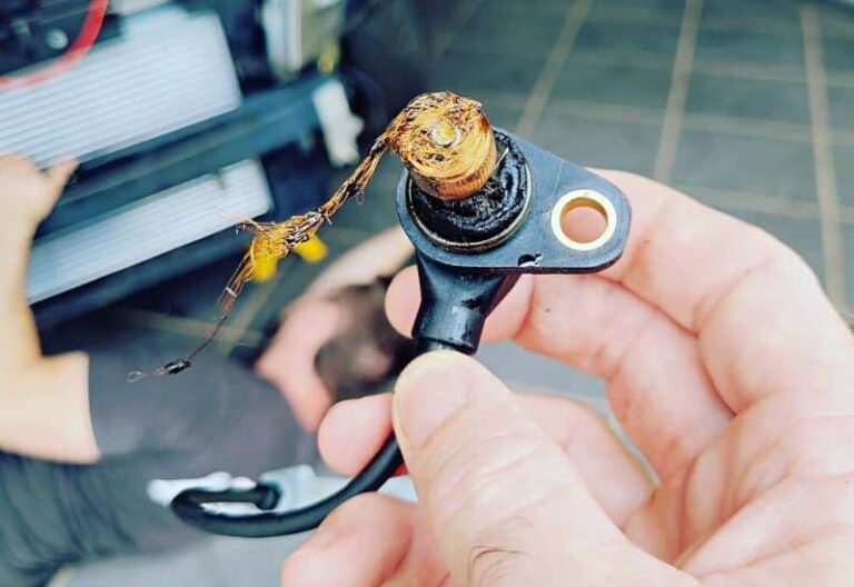
Look for cracks, physical damage, contamination, corrosion, loose mounting, and connector problems. Replace a damaged sensor rather than attempting to repair its internal piezoelectric element.
3. Inspect the harness
Check for broken wires, short circuits, poor terminal contact, damaged shielding, and routing problems. Compare every circuit against the vehicle wiring diagram.
4. Measure the sensor
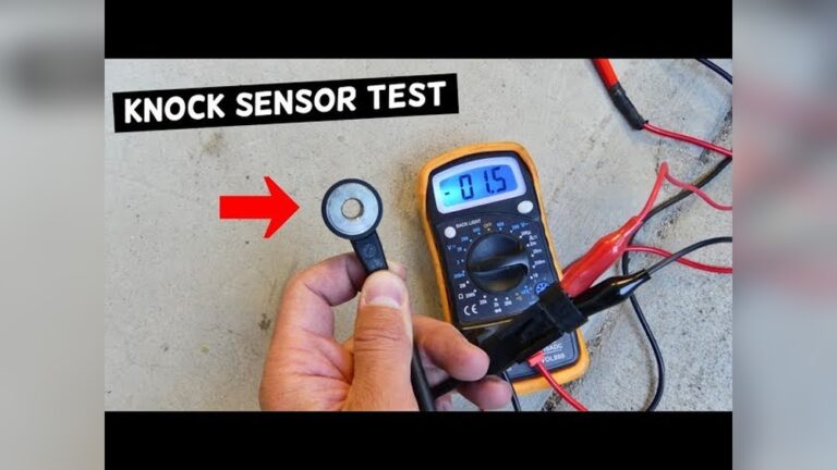
With the connector disconnected as required, measure the specified electrical characteristic. Some systems specify resistance, some capacitance, and others use different electrical tests.
5. Verify mounting
Clean the specified contact surface and install the sensor exactly as directed. Tighten the fastener to the manufacturer’s specified torque.
6. Perform required ECU procedures
Some vehicles require clearing diagnostic data, initializing a learning value, or completing a specified drive cycle after sensor replacement.
7. Confirm operation
Use the appropriate scan-tool data and diagnostic procedure to confirm that the fault does not return and that the ECU receives a plausible signal.
Do Not Use a Universal Resistance Value
A common mistake is assuming that every knock sensor should measure the same resistance. Published service procedures demonstrate that specifications vary. Some applications specify resistance in the megohm range, while others use different values or diagnostic methods.
For example, one Hyundai service procedure specifies approximately 5 megohms at 20 degrees Celsius and also provides a capacitance range. That value should be treated as an example for that application, not a universal knock-sensor specification.
Correct approach
Compare the measurement with the exact specification for the sensor and vehicle being serviced.
Incorrect approach
Do not condemn a sensor solely because its resistance differs from a number found for another engine.
How to Set Up an Aftermarket ECU Knock Sensor Calibration
Aftermarket ECU calibration is a different task from testing a factory knock sensor. If you are tuning an aftermarket engine-management system, you may need to tell the ECU what sensor is installed and how its signal should be interpreted.
The exact settings depend on the ECU and sensor. Typical configuration areas can include sensor type, frequency range, filtering, gain, detection thresholds, background-noise learning, and the amount of ignition retard commanded when knock is detected.
Knock sensors are designed to detect vibration in specific frequency ranges rather than simply produce a universal knock voltage. For example, Bosch publishes a motorsport knock sensor with a specified application frequency range of 3 to 30 kHz. That specification illustrates why sensor frequency characteristics matter when configuring an ECU.
Source: hopetownlodge.com
Identify the sensor
Confirm the exact sensor model and its documented electrical and frequency characteristics.
Configure the ECU input
Enter the sensor and input settings required by the ECU manufacturer rather than copying values from an unrelated setup.
Establish background noise
Use the ECU’s documented procedure to determine normal engine noise across the relevant operating range.
Set detection thresholds
Configure thresholds and filtering according to the ECU documentation and validated tuning methodology.
Validate conservatively
Confirm that genuine knock is detected without allowing excessive false detection from normal mechanical or combustion noise.
Why Frequency Filtering Matters
Engine vibration contains many frequencies. A knock-control system must distinguish combustion-related vibration from normal mechanical noise. The appropriate frequency band depends on the engine and sensor system, so a generic filter setting cannot be assumed to work for every engine.
A good calibration process therefore starts with documented sensor characteristics and the ECU manufacturer’s procedure. It should also account for the engine’s normal background noise at different speeds and loads.
Too sensitive
The system may interpret normal engine noise as knock and remove ignition timing unnecessarily.
Not sensitive enough
The ECU may fail to react quickly enough to genuine knock, reducing the protective value of knock control.
How to Check a Knock Sensor After Installation
After installing or servicing the sensor, verify the complete circuit before assuming the calibration is successful. A sensor can test correctly on the bench but still produce an incorrect ECU signal because of wiring damage, connector problems, incorrect mounting, or a fault elsewhere in the circuit.
Start by checking for diagnostic codes. Then follow the manufacturer’s signal or live-data procedure. If the service information provides a specific test condition, reproduce that condition rather than relying on an arbitrary engine speed or road test.
If the ECU reports a low or high knock-sensor input, diagnose the circuit before changing calibration settings. Electrical faults can mimic an incorrect calibration.
Source: autovehicleparts.com
No fault returns
A successful repair should remain free of the original fault under the conditions specified by the diagnostic procedure.
Signal is plausible
The measured or monitored signal should remain within the documented operating range for the application.
No harness fault
Continuity, insulation, shielding, and connector condition should meet the manufacturer’s requirements.
Correct mechanical installation
The sensor should remain securely mounted at the specified torque with the correct contact arrangement.
What If the Knock Sensor Code Returns?
If the same code returns, do not immediately increase or decrease the ECU knock threshold. Recheck the wiring, connector terminals, sensor condition, mounting torque, and power or ground circuits as applicable. Some diagnostic procedures specifically instruct the technician to check the harness before replacing the sensor or ECU.
A returned code can also indicate a problem outside the sensor itself. A damaged shielded wire, poor connector contact, or incorrect installation can change the signal enough for the ECU to identify a circuit fault.
P0325-type fault
Treat it as a knock-sensor circuit or performance diagnostic problem and follow the vehicle-specific diagnostic tree.
P0327-type fault
A low-input code can be caused by the sensor, wiring, connectors, or related circuit conditions.
P0328-type fault
A high-input code can also require circuit testing instead of simply replacing the sensor.
Common Knock Sensor Calibration Mistakes
Most calibration problems come from treating the knock sensor as a universal component. It is not. Sensor construction, electrical characteristics, mounting method, frequency response, ECU strategy, and diagnostic procedures vary by application.
Avoid changing ECU settings to compensate for a mechanical or electrical problem. A calibration change can hide a fault instead of fixing it. That is particularly risky when the adjustment reduces the ECU’s ability to recognize real knock.
Source: youtube.com
Using the wrong torque
A torque value from another vehicle or sensor can produce an incorrect mechanical coupling. Always use the application-specific specification.
Adding an unapproved washer
A washer or spacer can change how vibration reaches the sensor. Use only the hardware specified by the manufacturer.
Using generic electrical specifications
Resistance and capacitance values are not universal across knock sensors.
Ignoring the wiring
Open circuits, shorts, poor terminals, and damaged shielding can create symptoms that look like a sensor-calibration problem.
Testing by deliberately causing knock
Intentional detonation is not a safe substitute for a documented calibration or diagnostic procedure.
Changing thresholds before fixing faults
Correct the underlying sensor, wiring, installation, or ECU problem before modifying knock-detection sensitivity.
When You Should Replace Rather Than Calibrate the Sensor
A knock sensor is generally not a component that can be repaired internally. If it fails the manufacturer’s electrical or physical inspection, replacement is normally the appropriate remedy. A replacement should match the required application rather than simply fitting a sensor that physically appears similar.
Do not install a sensor that has been dropped or visibly damaged. Some service procedures specifically warn against using physically damaged sensors because the internal piezoelectric assembly can be affected even when the exterior looks acceptable.
After replacement, repeat the required installation and ECU procedures. Some vehicles require a learning-value initialization or other reset procedure, while others do not. The correct process is determined by the vehicle’s engine-management system.
Source: youtube.com
Replace a failed sensor
If the sensor does not meet the manufacturer’s specified test values, replacement is normally preferred over attempted repair.
Use the correct part
Match the sensor to the engine and ECU application, especially when frequency characteristics affect knock detection.
Follow post-replacement procedures
Perform any required ECU initialization, code clearing, learning, or drive-cycle procedure.
Signs the Problem May Not Be the Sensor
A recurring knock-sensor code does not automatically prove that the sensor itself has failed. Harness damage, connector corrosion, incorrect mounting, excessive mechanical noise, and ECU-related problems can all require investigation.
If the sensor passes its specified electrical tests but the ECU continues to report an implausible signal, continue through the diagnostic procedure instead of replacing parts at random.
Electrical fault
Check the circuit between the sensor and ECU according to the wiring diagram.
Mechanical fault
Verify sensor placement, contact surfaces, fastener condition, and specified torque.
ECU issue
Consider the ECU only after the prescribed sensor and circuit tests have been completed.
Frequently Asked Questions
Q
Can you calibrate a knock sensor?
Most factory knock sensors are not manually calibrated. The usual process is to verify the correct sensor, wiring, mounting, electrical characteristics, and ECU procedure. Aftermarket ECUs can provide adjustable knock-sensor calibration settings, but those settings must match the sensor and ECU documentation.
Q
How do I know if my knock sensor is working correctly?
Use the vehicle’s specified diagnostic procedure. Depending on the application, this may include resistance, capacitance, voltage, wiring, scan-tool data, or other tests. A generic multimeter reading alone is not enough to prove that a knock sensor is functioning correctly.
Q
What torque should a knock sensor be tightened to?
There is no universal torque specification. The correct value depends on the sensor and engine. Published service information shows different specifications across applications, so use the exact value for your vehicle or sensor rather than a general internet recommendation.
Q
Can a bad knock sensor cause poor engine performance?
It can. The knock sensor is part of the engine-control system, and a detected fault can cause the ECU to change its strategy or disable certain knock-control functions. Performance symptoms vary by vehicle, so diagnose the fault code and system rather than assuming the sensor is the only cause.
Q
Do I need a scan tool after replacing a knock sensor?
Often, a scan tool is useful for reading and clearing diagnostic trouble codes and confirming the repair. Some vehicles also require a learning or initialization procedure after replacement. Whether that step is necessary depends on the exact engine-management system.
Q
Can I test a knock sensor by tapping the engine?
A tap test is not a universal calibration method and can produce misleading results. Use the manufacturer’s specified diagnostic procedure instead. Do not deliberately create severe vibration or detonation as a substitute for proper testing.
✦ Wrapping Up
Conclusion
Learning how to calibrate knock sensor systems starts with an important distinction: most factory sensors are verified and correctly installed rather than manually adjusted. The reliable approach is to identify the exact application, inspect the sensor and wiring, perform the specified electrical tests, use the correct mounting torque, and complete any required ECU learning or diagnostic procedure.
Aftermarket ECU systems may require additional calibration of frequency filtering, signal gain, background noise, and knock thresholds. Those settings should be established from the actual sensor and ECU documentation and validated without intentionally damaging the engine.
If a knock-sensor fault remains after the basic checks, continue through the vehicle-specific diagnostic flow rather than changing knock thresholds or replacing unrelated components. When the required procedure involves advanced ECU tuning or uncertain engine-damage risk, use a qualified automotive technician or experienced tuner with the correct service and tuning information.
💡 Key Takeaway
Use the exact service or ECU documentation for your vehicle, verify the sensor and wiring first, torque the sensor to specification, complete required ECU procedures, and only then evaluate knock-control calibration.
Ethan Brooks is an automotive writer at Auto News 7, covering car news, vehicle maintenance, new model updates, recalls, and practical buying guides. He focuses on clear, useful information that helps drivers understand their vehicles and make better ownership decisions.
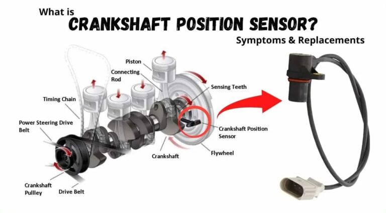
Can a crankshaft position sensor cause loss of power? Learn how a failing CKP sensor affects engine performance, common symptoms, diagnosis, and repair.