Test a single wire knock sensor by checking its sensor-to-ground resistance and verifying the signal wire and engine ground.
For drivers and DIY mechanics in the United States, a single wire knock sensor can often be checked with a digital multimeter before replacing the part. The sensor is usually mounted to the engine block and uses the engine itself as its electrical reference or ground. Because exact specifications vary by vehicle, the factory service information for the specific year, make, model, and engine should determine the final pass-or-fail value.
A useful test has more than one part. First, inspect the sensor, connector, and mounting area. Then test the sensor according to the manufacturer’s specified resistance or electrical test. Finally, check the single-wire circuit between the sensor and engine control module for continuity, unwanted shorts, and poor connections. Service procedures for different vehicles show why there is no universal resistance number for every single wire knock sensor.
Source: youtube.com
What Is a Single Wire Knock Sensor?
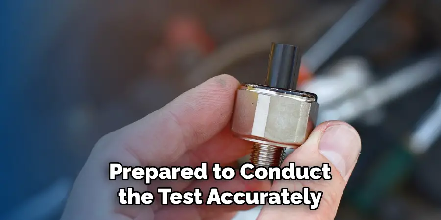
A single wire knock sensor is a vibration sensor used by the engine control system to detect combustion-related vibration commonly associated with engine knock. Many knock sensors use a piezoelectric element that converts vibration into an electrical signal for the engine control module.
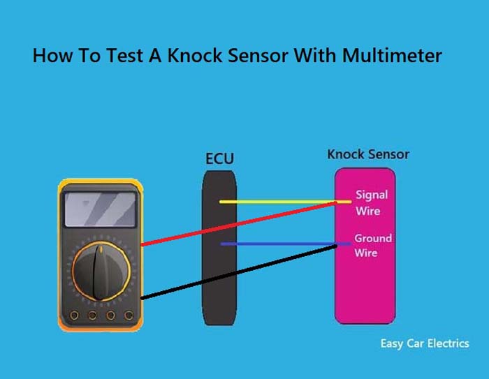
The key difference with a single wire design is the electrical return path. Instead of having separate signal and ground wires in the connector, the sensor can use its metal body and contact with the engine as the ground or reference path. The single wire then carries the sensor signal to the engine control module.
This design means the sensor mounting surface is part of the circuit. Corrosion, incorrect installation, excessive sealant, a damaged mounting surface, or a loose mounting bolt can therefore affect diagnosis.
Source: easycarelectrics.com
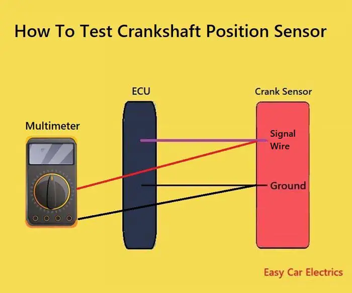
Sensor
Detects engine vibration and converts mechanical vibration into an electrical signal.
Single wire
Carries the sensor circuit connection toward the engine control module.
Engine block
Can provide the electrical reference or return path in a single wire design.
Engine control module
Receives and interprets the knock sensor signal as part of engine control and diagnostics.
Why the Vehicle Model Matters
There is no single resistance reading that proves every single wire knock sensor is good. Factory procedures differ. For example, published service procedures for some vehicles specify resistance limits in the hundreds of kilohms, while other systems use different electrical checks.
Some manufacturers also specify a voltage or signal check at the engine control module instead of relying only on an ohmmeter test. Always compare your measurement with the specification for the exact vehicle rather than a generic value found online.
Use the correct specification
Look up the year, make, model, engine, and applicable emissions configuration before interpreting the measurement.
Identify the correct terminal
Confirm which wire connects to the knock sensor before testing the circuit.
What You Need Before Testing
A digital multimeter is the main tool for a basic resistance and continuity inspection. You also need access to the vehicle-specific wiring diagram or service information so you can identify the sensor circuit and its expected values.
Perform resistance checks with the ignition switched off and the relevant connectors disconnected. Do not probe an energized circuit with the meter set to resistance because that can produce an incorrect reading and may damage the meter or vehicle electronics.
Digital multimeter
Use a meter capable of measuring the resistance range specified by the vehicle manufacturer.
Vehicle service information
Use it to find the sensor location, terminal identification, wiring path, resistance specification, and any special testing procedure.
Basic hand tools
You may need tools to access the sensor or disconnect its connector without damaging the wiring.
Safety equipment
Use appropriate eye protection and keep hands, clothing, and tools away from moving or hot engine components.
Safety Before You Start
Let the engine cool before working near the cylinder block or exhaust components. Keep the ignition off when performing resistance checks. If the sensor is difficult to reach, do not work around belts, fans, pulleys, or other moving components with the engine running.
Never assume that a sensor can be tested safely by tapping the engine or intentionally creating engine knock. A controlled electrical test is safer and gives more useful diagnostic information.
Ignition off
Switch the ignition off before disconnecting the sensor and measuring resistance.
Avoid unnecessary impact
Do not strike the sensor or engine block unless the vehicle manufacturer’s diagnostic procedure specifically calls for a controlled signal test.
How to Test a Single Wire Knock Sensor Step by Step
The most reliable approach is to separate the sensor test from the wiring test. This prevents a damaged wire or poor connection from being mistaken for a failed sensor.
The exact terminal and resistance specification must come from the vehicle-specific service information. The steps below describe the general diagnostic sequence used for a single wire design.
Source: youtube.com
Step 1: Locate the sensor
Find the knock sensor on the engine block using the vehicle’s service information. Confirm that it is actually a single wire design before testing.
Step 2: Inspect the sensor
Look for cracks, physical damage, corrosion, damaged threads, contamination, or signs that the sensor has been improperly installed.
Step 3: Disconnect the sensor
With the ignition off, disconnect the single wire from the sensor without pulling on the wire itself.
Step 4: Set the multimeter
Set the digital multimeter to resistance and select a range that includes the manufacturer’s specified sensor value.
Step 5: Measure the sensor
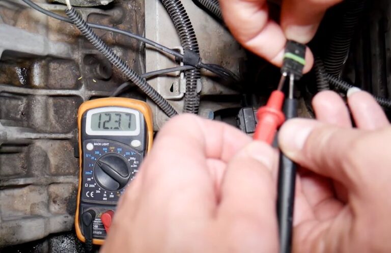
Place one meter probe on the sensor’s electrical terminal and the other on the sensor’s metal body or the specified engine-ground point, following the service manual.
Step 6: Compare the reading
Compare the measured value with the exact factory specification. Do not automatically condemn the sensor because a generic online value differs from your measurement.
Step 7: Test the wiring
If the sensor measurement is within specification, check continuity from the sensor wire to the appropriate engine control module terminal and check for unwanted shorts to ground or other circuits.
Step 8: Check the installation
Verify that the sensor mounting surface is clean and that the sensor is installed with the specified torque and installation method.
Step 1: Locate and Inspect the Knock Sensor
The sensor is commonly mounted directly to the engine block. Before connecting a meter, inspect the sensor and its surrounding area. Look for oil contamination, corrosion, damaged wiring, loose connections, or evidence that the sensor has been struck or damaged.
A visual inspection matters because electrical resistance alone cannot confirm correct mechanical installation. Some factory procedures specifically call for checking whether the sensor mounting bolt is secure.
Check the connector
Look for bent terminals, corrosion, loose pins, broken locks, or damaged insulation.
Check the mounting area
Make sure the sensor contacts the required engine surface as specified by the manufacturer.
Step 2: Measure Sensor Resistance
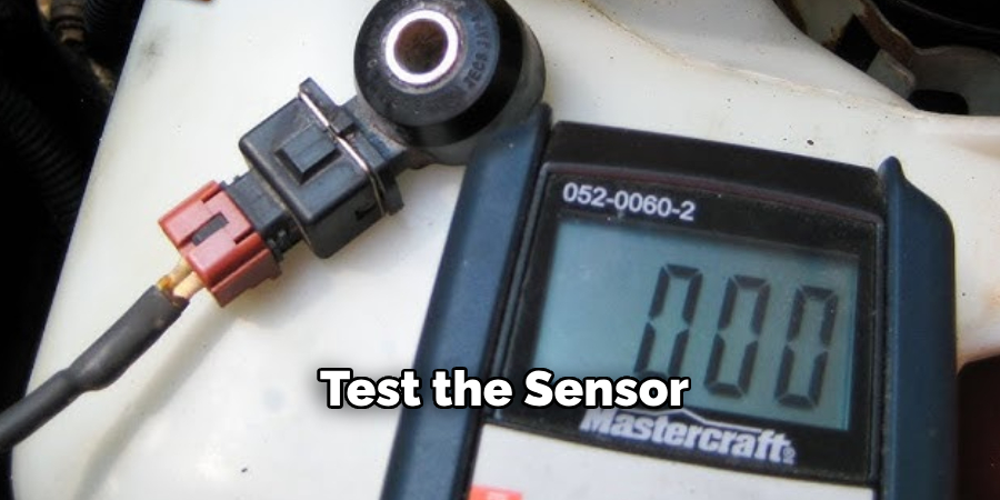
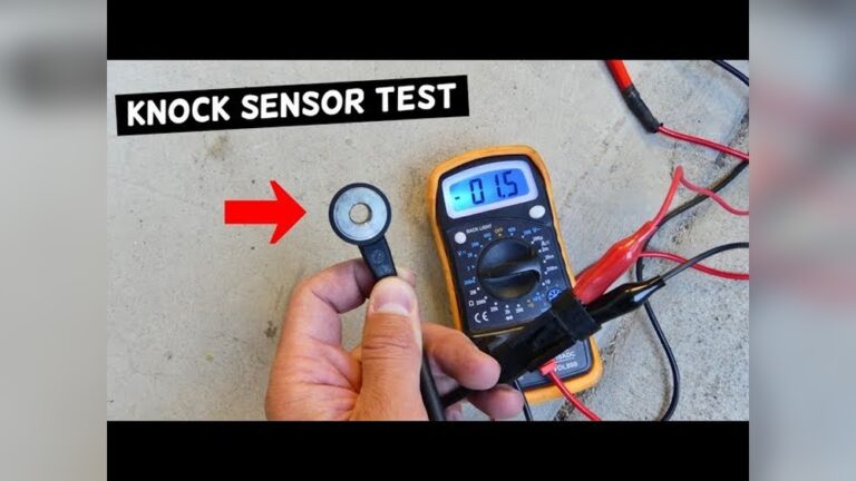
With the sensor disconnected and the ignition off, measure resistance between the sensor terminal and the specified ground point. On a single wire sensor, that ground point may be the sensor body or engine block.
The reading must be interpreted against the vehicle’s factory specification. Some documented service procedures use a threshold in the hundreds of kilohms, while other sensors and systems have different specifications. A generic resistance number cannot safely be applied to every vehicle.
Within specification
A reading inside the manufacturer’s specified range supports the sensor passing the resistance portion of the test, but it does not prove the entire circuit is good.
Open or far outside specification
An open circuit or a reading outside the specified range can indicate a faulty sensor, but verify the meter setup, temperature conditions, and test points first.
Unexpected low resistance
A reading substantially below the specified range can indicate an internal fault or a measurement problem and should be checked against the manufacturer’s procedure.
How to Test the Single Wire Knock Sensor Circuit
A sensor that measures correctly can still have a circuit problem. The next step is to test the wire between the knock sensor and the engine control module, using the wiring diagram to identify the correct terminals.
With the relevant connectors disconnected and the ignition off, check continuity through the signal wire. Then check that the wire is not unintentionally shorted to engine ground, battery voltage, another circuit, or a shield where the wiring design requires separation.
Source: carandtruck.org
Check continuity
Measure resistance from the sensor-side terminal to the correct engine control module terminal. Use the manufacturer’s allowable resistance rather than assuming that every vehicle has the same limit.
Check for a short to ground
Verify that the signal wire is not unintentionally connected to ground when the service procedure requires the circuit to be isolated.
Check for a short to power
Inspect the circuit for unwanted voltage or contact with another powered circuit when the manufacturer’s diagnostic procedure calls for this check.
Inspect connectors
A loose or corroded terminal can create an intermittent fault even when the wire itself has continuity.
Why a Good Sensor Can Still Trigger a Knock Sensor Code
A diagnostic trouble code does not automatically prove that the sensor itself has failed. Depending on the vehicle, the fault may involve the sensor circuit, connector, wiring, grounding path, sensor installation, or engine control module input.
Factory diagnostic procedures commonly separate the sensor check from the harness check for this reason. Testing the complete circuit helps prevent replacing a functioning sensor when the real problem is in the wiring.
Open circuit
A broken wire can prevent the sensor signal from reaching the engine control module.
Short circuit
Contact with ground, power, or another circuit can distort the signal.
Poor connection
Corroded or loose terminals can create intermittent sensor faults.
Mounting problem
Incorrect sensor installation can affect how engine vibration reaches the sensing element.
How to Interpret Your Multimeter Results
The result should be classified by comparing it with the manufacturer’s specification rather than by using a universal pass-or-fail number. The table below provides a diagnostic framework, not a substitute for the vehicle’s service manual.
Source: youtube.com
Specified resistance
If the sensor is within the documented range, continue with wiring, connector, installation, and signal checks if a fault remains.
Open circuit
If the meter shows no continuity where the specification requires a measurable resistance, verify the test points and meter operation before considering sensor replacement.
Resistance below specification
An unusually low reading may indicate an internal sensor fault or an incorrect measurement setup. Confirm the manufacturer’s test method.
Normal sensor but circuit fault
If the sensor passes but the wire fails continuity or isolation testing, focus on the harness, connector, or circuit rather than replacing the sensor immediately.
Do Not Confuse Continuity With Sensor Health
A continuity beep only tells you that the meter detects a conductive path under its test conditions. It does not prove that a knock sensor produces the correct signal under engine operating conditions.
Likewise, a resistance measurement can identify certain internal faults but cannot reproduce every dynamic condition the sensor experiences while the engine is running. If the basic resistance and wiring checks pass but the vehicle still reports a knock sensor fault, follow the manufacturer’s complete diagnostic procedure.
Resistance is one test
Use it as part of a diagnostic sequence rather than as the only proof that the sensor works.
Signal testing may be required
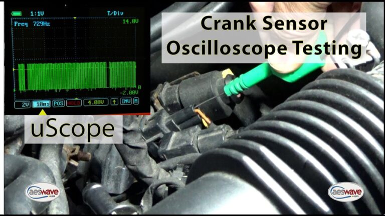
Some vehicles require a voltage or waveform check at the sensor or engine control module.
Common Mistakes When Testing a Single Wire Knock Sensor
Most incorrect diagnoses come from using the wrong specification, testing the wrong terminal, leaving the circuit connected during a resistance test, or overlooking the sensor’s mounting and ground path.
Avoid replacing the sensor based on a generic internet resistance value. Factory specifications can vary substantially between vehicles, and even the correct test points can differ by engine.
Source: safetywish.com
Using the wrong resistance specification
A value for another engine or sensor can lead to a false diagnosis.
Testing with the ignition on
Resistance testing should normally be performed with the relevant circuit de-energized.
Leaving the connector connected
Connected electronics can change the measurement and may expose the meter to conditions it was not intended to measure in resistance mode.
Ignoring the mounting surface
A single wire design can depend on the sensor body and engine contact for its electrical return path.
Replacing the sensor before checking wiring
A broken, shorted, or poorly connected wire can produce a sensor fault even when the sensor itself is functional.
Forcing a test procedure from another vehicle
Knock sensor circuits differ between manufacturers and engine families, so a procedure must match the vehicle being diagnosed.
What to Do If the Test Shows a Fault
If the sensor is clearly outside the vehicle manufacturer’s specification, replacement may be appropriate after confirming the meter, test temperature, and measurement points. If the sensor passes but the wiring fails, repair the circuit and retest before replacing the sensor.
If both the sensor and wiring pass but the diagnostic trouble code returns, continue with the vehicle-specific diagnostic procedure. The next checks may include the engine control module input circuit, connector condition, sensor installation, power or reference circuits, and an operating signal test.
Source: safetyfic.com
Sensor fails resistance test
Confirm the specification and measurement procedure, then replace the sensor if the factory procedure identifies it as defective.
Wire fails continuity test
Repair the open circuit or high-resistance connection and verify the repair.
Wire is shorted
Locate and repair the short according to the wiring diagram before condemning the sensor.
Everything passes
Follow the vehicle-specific signal and diagnostic trouble code procedure instead of repeatedly replacing parts.
When Professional Diagnosis Makes Sense
Consider professional diagnosis when the sensor is difficult to access, the wiring is buried in the harness, the engine control module requires specialized signal testing, or the fault persists after basic checks. A technician with the correct service information and diagnostic equipment can test the circuit without relying on guesswork.
Stop if testing requires procedures that you cannot perform safely. Electrical diagnosis around an operating engine can involve hot surfaces, moving components, and energized circuits.
Persistent fault
Get additional diagnosis when the sensor and wiring pass but the code continues to return.
Difficult access
Use professional service when reaching the sensor requires unsafe work around hot or moving engine components.
A Practical Diagnostic Sequence
For a straightforward diagnosis, work from the simplest checks toward the more involved ones. Start with identification and visual inspection, then test the sensor, followed by the wiring and finally any vehicle-specific signal checks.
This sequence reduces unnecessary parts replacement because each step helps separate a sensor problem from a circuit problem. The factory service procedure should take priority whenever it gives a different order or test.
Identify
Confirm the engine, sensor type, connector, terminal, and factory specification.
Inspect
Check the sensor, mounting surface, connector, and visible wiring.
Test
Measure sensor resistance using the specified test points and conditions.
Verify
Check wire continuity, unwanted shorts, connector condition, and the engine ground path as applicable.
Confirm
Use the vehicle’s signal or scan-tool diagnostic procedure when the basic tests do not identify the problem.
Frequently Asked Questions
Q
How do you test a single wire knock sensor with a multimeter?
Disconnect the sensor with the ignition off, set the multimeter to resistance, and measure between the sensor terminal and the specified engine-ground point. Compare the result with the exact specification for the vehicle.
Then test the single wire between the sensor and engine control module for continuity and unwanted shorts if the sensor passes.
Q
What resistance should a single wire knock sensor have?
There is no universal resistance value for every single wire knock sensor. Published manufacturer procedures show that specifications can vary by vehicle and sensor design.
Use the service information for the exact year, make, model, engine, and applicable configuration rather than relying on a generic number.
Q
Can a single wire knock sensor use the engine block as ground?
Yes. A single wire design can use the sensor body and its contact with the engine as the electrical return or reference path. That is why the sensor mounting condition can matter during diagnosis.
The exact circuit arrangement should still be confirmed with the vehicle’s wiring diagram.
Q
Can a bad knock sensor cause a check engine light?
It can, depending on the vehicle and the diagnostic strategy used by its engine control system. Knock sensor circuit faults may be associated with diagnostic trouble codes such as P0325-series codes on some vehicles.
A stored code identifies a monitored circuit or condition, not automatically a failed sensor. Testing the sensor and circuit is necessary to identify the actual fault.
Q
What if the knock sensor resistance is good but the code remains?
Check the sensor wiring, connectors, engine ground or mounting condition, and the engine control module circuit according to the factory diagnostic procedure. A resistance test does not verify every operating characteristic of the sensor.
If the basic checks pass, the vehicle may require a signal or scan-tool test to identify an intermittent or dynamic fault.
Q
Should I replace a knock sensor if the resistance is different from an online value?
No. Do not replace the sensor solely because its reading differs from a value found for another vehicle or sensor. Knock sensor specifications vary.
First verify the correct factory specification, test points, temperature conditions, and meter range for your exact vehicle.
✦ Wrapping Up
Conclusion
Testing a single wire knock sensor starts with understanding that the sensor, single signal wire, engine ground or mounting path, connector, and engine control module circuit can all affect the diagnosis. A multimeter can provide useful information, but the reading must be compared with the vehicle-specific service specification.
For the most reliable diagnosis, inspect the sensor first, perform the specified resistance test with the circuit de-energized, then check the wiring and connectors. If those checks pass and the fault remains, use the manufacturer’s signal and diagnostic procedure instead of replacing parts based only on a generic test value.
💡 Key Takeaway
Use the exact factory specification for your vehicle, test the disconnected sensor first, verify the single-wire circuit next, and stop short of replacing the sensor until the complete diagnostic sequence supports that conclusion.
Ethan Brooks is an automotive writer at Auto News 7, covering car news, vehicle maintenance, new model updates, recalls, and practical buying guides. He focuses on clear, useful information that helps drivers understand their vehicles and make better ownership decisions.
Learn how to test camshaft position sensor wiring with a multimeter. Follow a safe step-by-step process to check power, ground, signal circuits, and common wiring faults.