Test a Chevy crankshaft position sensor by checking scan-tool RPM, power and ground, the signal circuit, wiring, and sensor operation.
If you are diagnosing a Chevrolet car, truck, or SUV in the United States, a crankshaft position sensor problem can cause hard starting, stalling, a no-start condition, or an illuminated check engine light. The exact test depends on the Chevy model, engine, year, and sensor design, so there is no single resistance value or pinout that applies to every Chevrolet vehicle.
The most useful first test is often a scan-tool check while the engine cranks. Many Chevrolet service procedures expect the engine-speed parameter to show a nonzero RPM signal during cranking. If the scan tool shows no engine speed, the CKP sensor circuit, wiring, power supply, ground, reluctor, or sensor itself needs further testing.
This guide explains how to test crankshaft position sensor Chevy systems without assuming a universal wiring layout. For a precise terminal number, voltage specification, or component test, use the service information for the exact year, model, engine, and sensor.
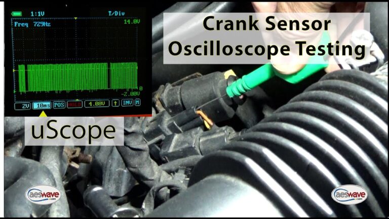
Source: 1aauto.com
What Does a Chevy Crankshaft Position Sensor Do?
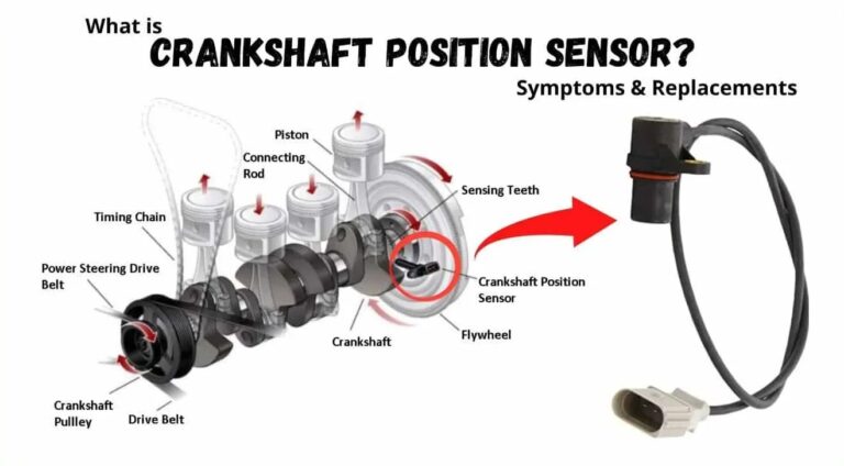
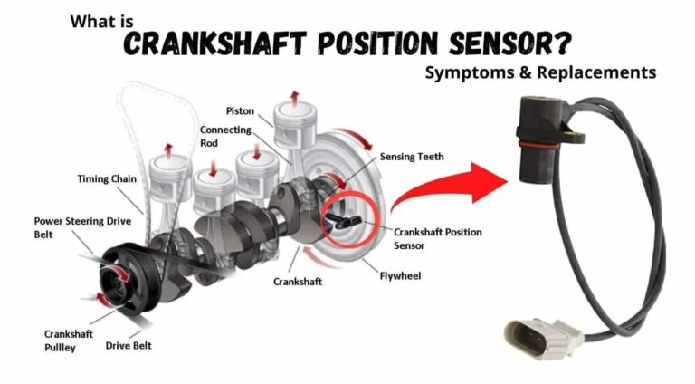
The crankshaft position sensor, commonly called the CKP sensor, tells the engine control module where the crankshaft is positioned and how fast it is rotating. The ECM uses this information for engine timing and other control functions. If the ECM cannot receive a valid crankshaft signal, the engine may crank without starting or may run poorly or stall.
Chevrolet has used different CKP sensor designs across its cars, trucks, and SUVs. Some applications use a Hall-effect sensor with a power or reference circuit, ground, and digital signal. Other applications can use different sensing arrangements. That difference matters because a test procedure that is correct for one Chevy engine can be wrong for another.
A diagnostic trouble code such as P0335 points to a crankshaft position sensor circuit problem, but it does not automatically prove that the sensor itself has failed. The code and symptoms should be followed by circuit testing.
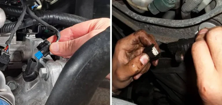
Source: mechlesson.com
CKP sensor
Detects crankshaft position and rotation and sends a corresponding signal to the engine control module.
ECM
Processes the CKP signal along with other engine inputs to control engine operation.
Reluctor
A toothed or specially shaped rotating component creates the changing magnetic or electrical conditions detected by the CKP sensor.
CKP circuit
Includes the sensor, connector, wiring, reference or supply circuit, ground or low reference, and signal circuit.
Common Signs of a Bad Chevy CKP Sensor
Common symptoms can include an engine that cranks but does not start, intermittent stalling, difficult starting, hesitation, or a check engine light. Some failures appear only when the sensor or wiring becomes hot, so the vehicle may work normally and then develop a no-start or stall condition.
These symptoms are not unique to the crankshaft position sensor. A weak battery, ignition problem, fuel problem, camshaft sensor issue, damaged wiring, or another engine-control fault can produce similar symptoms.
No-start condition
The starter turns the engine, but the ECM may not receive the crankshaft signal needed for normal engine control.
Intermittent stalling
A failing sensor or connection can lose its signal while the engine is running.
Check engine light
A CKP-related diagnostic trouble code may be stored, although other codes or no code at all can occur depending on the failure.
Before You Test the Crankshaft Position Sensor
Identify the exact Chevrolet vehicle before connecting a meter or probing a connector. Record the model year, model, engine size, and engine code when available. The connector pin arrangement and specified voltage tests can differ between Chevrolet applications.
Gather a digital multimeter, a compatible OBD-II scan tool, wiring information for the exact vehicle, back-probing leads or suitable connector test adapters, and basic hand tools if sensor removal is required. A test light should not be substituted for a multimeter when the service procedure calls for a precise voltage measurement.
Work with the vehicle securely parked. Keep loose clothing, hands, test leads, and tools away from belts, pulleys, fans, and other moving components while the engine is running. If you must work near the starter or rotating engine parts, use the vehicle manufacturer’s safety procedure.
Source: animalia-life.club
Verify the vehicle
Confirm the Chevrolet year, model, engine, and applicable wiring diagram before identifying sensor terminals.
Use a scan tool when possible
A scan tool can reveal engine RPM during cranking and may provide CKP-related data that a simple resistance test cannot show.
Inspect first
Look for damaged insulation, oil contamination, corrosion, loose terminals, broken retaining clips, or wiring routed too close to possible sources of electrical interference.
Protect the connector
Use proper back-probing techniques and avoid spreading or damaging terminals.
Why You Should Not Start With a Resistance Test
A resistance test is not a universal CKP test for Chevrolet vehicles. A specification that applies to a particular passive sensor may not apply to a three-wire Hall-effect sensor. Measuring resistance across the wrong terminals can also lead to a false diagnosis.
For many Chevrolet applications, the more useful first checks are scan-tool engine RPM, circuit reference voltage, low reference or ground integrity, signal voltage, and sensor operation. Use resistance measurements only when the service information for the specific vehicle calls for them.
Sensor design matters
Different CKP technologies require different diagnostic methods.
Pinouts vary
Do not assume terminal numbers from another Chevy model are correct for your vehicle.
How to Test Crankshaft Position Sensor Chevy With a Scan Tool
The scan-tool RPM test is a strong starting point because it checks whether the engine control system is receiving a usable crankshaft-speed signal during cranking. Connect the scan tool, select live data, locate Engine Speed or RPM, and watch the reading while the starter turns the engine.
If the scan tool displays a nonzero engine-speed reading during cranking, the ECM is receiving some crankshaft-speed information. That does not prove the sensor is perfect, but it makes a completely missing CKP signal less likely. If the engine cranks and the scan tool remains at zero RPM, continue with circuit and sensor testing rather than immediately replacing the sensor.
Some Chevrolet service procedures also provide CKP active counters or CKP-related data. On applicable systems, the counter should respond as the sensor detects the rotating reluctor. The exact parameter name and expected behavior depend on the vehicle.
Source: youtube.com
Step 1: Connect the scan tool
Connect a compatible diagnostic scan tool to the vehicle’s diagnostic connector and turn the ignition on.
Step 2: Open live data
Locate Engine Speed, RPM, CKP, or other crankshaft-related parameters supported by the vehicle.
Step 3: Crank the engine
Observe the data while the starter turns the engine. Follow the vehicle’s normal starting procedure and keep clear of moving components.
Step 4: Interpret the result
A nonzero RPM reading shows that the ECM is receiving crankshaft-speed information. Zero RPM requires further diagnosis of the CKP circuit and related components.
Step 5: Check stored codes
Record CKP-related trouble codes and freeze-frame information before clearing codes.
What P0335 Means on a Chevy
P0335 is associated with a crankshaft position sensor circuit malfunction. The code tells you where the control system detected a problem, not necessarily which physical component must be replaced.
If P0335 is present, inspect the CKP wiring and connector, verify the required reference or supply circuit, verify the low reference or ground circuit, and test the signal according to the vehicle-specific service procedure.
P0335 does not automatically mean sensor failure
A wiring fault, connector problem, missing reference voltage, poor ground, reluctor problem, or control-module issue can also prevent a valid CKP signal.
Use other codes as clues
Additional power or reference-voltage codes can change the diagnostic sequence and should be addressed according to the applicable service procedure.
How to Test a Chevy CKP Sensor With a Multimeter
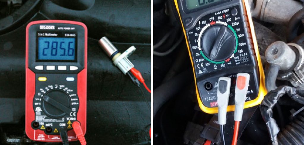
A multimeter can help determine whether the CKP circuit has the required voltage and ground connections and whether the signal circuit behaves as expected. The exact values must come from the service information for the specific Chevrolet engine.
On many three-wire Hall-effect Chevrolet CKP systems, the circuit contains a 5-volt reference, a low reference, and a signal circuit. Some documented GM procedures specify approximately 4.8 to 5.2 volts for both the reference and signal circuit checks under particular test conditions. That range is an example of a vehicle-specific service specification, not a universal value for every Chevy.
Turn the ignition off before disconnecting the sensor connector. With the connector disconnected, identify the terminals using the exact wiring diagram for the vehicle. Do not insert meter probes into terminals by guesswork.
Source: hitchesguide.com
Check the low reference
With the sensor disconnected and ignition off, test the low-reference circuit as specified by the vehicle service procedure. Some GM procedures require very low resistance between the low-reference circuit and ground.
Check the reference voltage
With the ignition on and the connector in the required test configuration, measure the reference circuit against the specified ground. Some three-wire GM CKP procedures specify about 4.8 to 5.2 volts.
Check the signal circuit
Measure the signal circuit using the exact test conditions and terminal identification specified for the vehicle. Do not apply a generic voltage value to a different CKP design.
Inspect for wiring faults
If a voltage is missing, trace the circuit for an open, short to ground, short to voltage, high resistance, damaged insulation, or poor connector contact before condemning the sensor.
Testing a Three-Wire Hall-Effect CKP Sensor
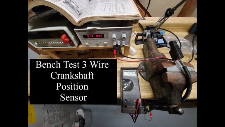
For a three-wire Hall-effect sensor, the sensor normally depends on an electrical supply or reference, a low reference, and a signal circuit. The sensor changes the signal as the reluctor passes the sensing element. The ECM interprets those changes as crankshaft position and speed information.
A useful diagnostic sequence is to verify the reference voltage first, verify the low-reference circuit, and then verify the signal circuit. If the required circuits are correct but the sensor does not produce the expected response under the manufacturer’s component test, the sensor becomes a stronger suspect.
Do not confuse terminals
Terminal numbers and wire colors are application-specific. Use the exact wiring diagram rather than copying a pinout from another Chevy.
Avoid short circuits
Back-probe carefully and use fused test equipment or adapters when the service procedure calls for them.
Can You Test a CKP Sensor for Resistance?
You can test resistance only when the sensor design and service procedure call for it. A passive magnetic sensor may have a specified resistance range, while a Hall-effect sensor uses an electronic circuit and should not be judged by the same resistance test.
If the manufacturer’s diagnostic procedure does not specify a resistance test, do not use a generic online resistance value to decide whether the sensor is good or bad.
Use resistance only when specified
Follow the exact component test for the Chevrolet engine being diagnosed.
Never measure resistance on a powered circuit
Turn the ignition off and isolate the circuit as required before using the resistance function.
How to Tell Whether the Sensor or Wiring Is Bad
A missing CKP signal does not automatically mean the sensor is defective. The sensor can be electrically sound while the connector, wiring, reference supply, ground, reluctor, or installation is faulty. Diagnose the complete circuit before replacing an expensive or difficult-to-access component.
Inspect the sensor connector for corrosion, bent terminals, pushed-back terminals, broken locks, oil contamination, and loose connections. Follow the harness back from the sensor and look for rubbing, melting, cuts, stretched wiring, or aftermarket wiring installed too close to the sensor circuit.
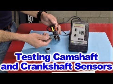
If the wiring checks correctly, perform the vehicle-specific CKP component test. Some Chevrolet service procedures use scan-tool CKP active counters and a controlled test with the sensor connected. On applicable systems, passing a suitable flat steel object across the sensor tip should cause the active counter to increment. This test is application-specific and should not be substituted for the procedure on a different sensor design.
Source: youtube.com
Sensor connector
Check for corrosion, loose terminals, physical damage, and poor terminal tension.
Harness
Inspect for opens, shorts, damaged insulation, chafing, heat damage, and electrical interference.
Reluctor
A damaged, incorrectly positioned, or contaminated reluctor can prevent the sensor from generating the expected pattern.
Sensor installation
Verify that the sensor is correctly seated and secured and that any required O-ring or mounting component is in good condition.
A Simple Diagnostic Decision Path
Use the test results to narrow the fault instead of replacing parts based only on symptoms. If the scan tool shows RPM while cranking, investigate other causes if the engine still will not start. If RPM stays at zero, continue with CKP circuit testing.
If the required reference voltage or ground is missing, repair the circuit before replacing the sensor. If the circuit supplies and wiring are correct but the sensor fails the specified component test, sensor replacement may be appropriate. If the sensor and circuits pass, investigate the reluctor, mechanical timing, ECM inputs, and other related systems.
RPM present
The ECM is receiving crankshaft-speed information, so a completely missing CKP signal is less likely. Continue diagnosing the actual starting or running complaint.
RPM absent
Check the CKP reference or supply, low reference, signal circuit, connector, sensor, and reluctor according to the applicable procedure.
Reference voltage missing
Trace the reference circuit and related power or sensor circuits before replacing the CKP sensor.
Circuit passes but sensor fails
A failed sensor becomes more likely when the complete circuit and component test meet the conditions for condemning the sensor.
Common Mistakes When Testing a Chevy Crankshaft Sensor
The most common diagnostic mistake is treating every Chevrolet crankshaft position sensor as though it has the same wiring and electrical characteristics. Chevrolet has used multiple engine and sensor configurations, so the correct test must match the vehicle.
Another mistake is replacing the sensor immediately after reading P0335. A diagnostic code identifies a monitored fault but does not necessarily identify the failed physical component. Checking the circuit first can prevent unnecessary parts replacement.
Do not probe connectors aggressively or short a reference circuit to ground without following the manufacturer’s procedure. A damaged connector or incorrectly performed jumper test can create additional faults and make the original problem harder to diagnose.
Source: ar.inspiredpencil.com
Using a generic pinout
Pin numbers and wire colors can vary by model and engine.
Using a generic resistance value
Resistance specifications are not interchangeable between different CKP sensor designs.
Replacing the sensor based only on P0335
A CKP circuit code can be caused by wiring, connector, reference voltage, ground, reluctor, or control-system problems.
Testing resistance with power applied
Resistance measurements should be performed with the circuit powered down and isolated as required.
Ignoring the battery
Low battery voltage can affect cranking speed and may complicate starting-system and scan-tool observations.
When Professional Diagnosis Makes Sense
Consider professional diagnostic help when the vehicle has intermittent CKP faults, difficult connector access, suspected reluctor damage, wiring faults inside a harness, or conflicting scan-tool and multimeter results. A technician with the correct factory-level service information and diagnostic equipment can test the circuit without relying on generic specifications.
Stop if a test requires working around unsafe moving parts, fuel, high-temperature components, or electrical circuits that you cannot safely identify. The goal is to locate the fault without creating a second problem.
Intermittent problem
A fault that appears only when hot or when the harness moves can require advanced testing and careful observation.
Mechanical suspicion
If the sensor and electrical circuits pass but the signal remains incorrect, the reluctor or related mechanical timing components may need inspection.
What to Do After Testing the CKP Sensor
After repairing a CKP circuit or replacing a sensor, clear diagnostic trouble codes only after recording the original codes and freeze-frame information. Start the vehicle and confirm that the engine-speed and CKP data behave normally when the applicable scan-tool parameters are available.
The final verification should match the original complaint. If the vehicle previously stalled when hot, verify operation under the conditions that produced the failure when it is safe to do so. If it had a no-start condition, confirm that it starts consistently and that the relevant diagnostic codes do not return.
If the CKP sensor and circuits pass but the original problem remains, do not continue replacing CKP components without new evidence. Move to other systems that can produce the same symptom, such as ignition, fuel delivery, camshaft position, engine timing, compression, or other control-system faults.
Source: safetyfic.com
Clear and recheck codes
After recording diagnostic information and completing repairs, clear applicable codes and verify whether the fault returns.
Verify scan data
Check engine speed and available CKP-related data to confirm that the repaired circuit is behaving normally.
Repeat the original condition
If the fault was intermittent, verify the repair under the same general operating conditions without creating an unsafe situation.
Continue diagnosis if needed
A passing CKP test means another cause should be investigated rather than repeatedly replacing the same component.
Frequently Asked Questions
Q
How do I test a crankshaft position sensor on a Chevy?
Start by checking the scan-tool engine-speed parameter while the engine cranks. If RPM is missing, inspect the CKP connector and wiring, then test the reference or supply, low reference, and signal circuits using the exact procedure for the Chevy’s year, model, and engine.
A multimeter can verify circuit voltages, but the correct specifications depend on the sensor design. Do not use a generic pinout or resistance value.
Q
What should RPM show when a Chevy is cranking?
On Chevrolet applications that use engine-speed data from the CKP system, the scan tool should normally show a nonzero engine-speed value while the engine is cranking. The exact cranking RPM varies with the engine, battery condition, starter, temperature, and other factors.
If the scan tool remains at zero RPM during cranking, perform the applicable CKP circuit diagnosis rather than assuming the sensor itself is defective.
Q
Can P0335 on a Chevy mean something other than a bad crankshaft sensor?
Yes. P0335 identifies a crankshaft position sensor circuit malfunction, but the root cause can involve the sensor, connector, wiring, reference voltage, low reference, signal circuit, reluctor, or another related control-system fault.
Test the circuit before replacing the sensor so that a wiring or power-supply problem is not mistaken for a failed component.
Q
What voltage should a Chevy crankshaft position sensor have?
There is no single voltage specification for every Chevrolet CKP sensor. Many three-wire Hall-effect applications use a 5-volt reference circuit, and some documented GM procedures specify approximately 4.8 to 5.2 volts under their stated test conditions.
Use the wiring diagram and service procedure for the exact vehicle. Measuring the wrong terminal or applying a specification from another engine can produce a false diagnosis.
Q
Can I test a Chevy crankshaft position sensor with a multimeter?
Yes, a multimeter can be useful for checking CKP circuit voltage, ground or low-reference integrity, continuity, and other tests specified for the vehicle. The meter can help determine whether the sensor is receiving the electrical conditions it needs to operate.
It should not be used with a generic test procedure for every Chevy. Sensor type and circuit design determine which measurements are valid.
Q
Should I replace the crankshaft sensor if the scan tool shows zero RPM?
Not immediately. Zero RPM during cranking is evidence that the ECM is not receiving the expected engine-speed information, but the cause can be the sensor, wiring, connector, reference circuit, low reference, reluctor, or another related fault.
Use the vehicle-specific circuit and component tests to identify the actual failure before replacing the sensor.
✦ Wrapping Up
Conclusion
The safest way to test a crankshaft position sensor Chevy system is to diagnose the complete circuit rather than rely on a single resistance reading or a trouble code. Start with scan-tool data, especially engine RPM during cranking, then inspect the connector and wiring and perform the specified voltage and component tests.
Because Chevrolet has used different CKP sensor designs across its vehicles, the exact terminal numbers and electrical specifications must come from the service information for the specific year, model, and engine. A failed sensor is only one possible cause of a missing crankshaft signal.
If the sensor, wiring, and circuit tests pass, continue to other possible causes instead of replacing additional CKP components without evidence. This approach can reduce unnecessary parts replacement and lead to a more accurate diagnosis.
💡 Key Takeaway
Identify the exact Chevy engine, check live RPM while cranking, then test the CKP power or reference, low reference, signal circuit, wiring, and sensor according to the vehicle-specific service procedure.
Ethan Brooks is an automotive writer at Auto News 7, covering car news, vehicle maintenance, new model updates, recalls, and practical buying guides. He focuses on clear, useful information that helps drivers understand their vehicles and make better ownership decisions.
Learn how to fix a crankshaft position sensor with step-by-step diagnostics, testing, wiring checks, replacement tips, common symptoms, and troubleshooting advice for U.S. vehicle owners.
Learn how to remove crankshaft position sensor safely and correctly. Follow step-by-step instructions, tools needed, troubleshooting tips, and common mistakes to avoid.