Repairing a crankshaft sensor usually means diagnosing its circuit first, then repairing wiring or replacing the failed sensor.
For drivers in the United States, a faulty crankshaft position sensor can cause hard starting, stalling, poor engine operation, or a no-start condition. The crankshaft position sensor, often called the CKP sensor, tells the engine computer where the crankshaft is and how fast it is turning. Without a reliable signal, the powertrain control module may not be able to control ignition and fuel delivery correctly.
The key point is that a crankshaft sensor fault does not always mean the sensor itself is bad. A damaged wire, corroded connector, poor electrical connection, incorrect installation, or a related engine problem can create similar symptoms and diagnostic trouble codes. The safest approach is to diagnose the circuit before buying a replacement part.
This guide explains how to repair a crankshaft sensor problem on a typical gasoline vehicle. Exact sensor locations, wiring tests, fastener sizes, torque values, relearn procedures, and removal steps vary by year, make, model, and engine. Always use the vehicle manufacturer’s service information for specifications that are specific to your vehicle.
Source: y-ic.com
What Does a Crankshaft Position Sensor Do?
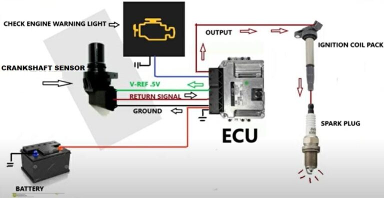
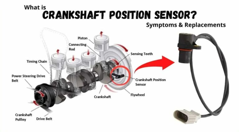
The crankshaft position sensor monitors crankshaft position and rotational speed. Its signal is used by the engine computer to coordinate functions such as ignition timing and fuel injection. Depending on the vehicle, the sensor may use a magnetic pickup, Hall-effect design, or another electronic sensing method.
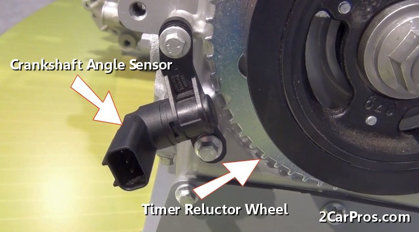
The sensor is commonly mounted near the crankshaft, crankshaft pulley, flywheel, or transmission bellhousing. Some engines place it behind another component, so access can range from simple to difficult. The exact location should be confirmed with the service information for the vehicle.
Because the CKP signal is fundamental to engine operation, a failed or intermittent signal can cause symptoms that appear more serious than a simple sensor fault. Diagnosis should therefore start with the complete circuit rather than assuming the sensor is automatically the problem.
Source: 2carpros.com
Crankshaft position
The sensor provides the engine computer with information about crankshaft position so engine timing can be coordinated.
Engine speed
The crankshaft signal also provides information about rotational speed during cranking and engine operation.
Ignition and fuel control
The engine computer uses crankshaft information as part of the control strategy for ignition and fuel delivery.
Symptoms of a Bad Crankshaft Sensor
A failing crankshaft sensor can produce several symptoms, but none of them proves that the sensor itself has failed. Hard starting, intermittent stalling, an engine that cranks without starting, misfires, or an illuminated Check Engine Light can have many possible causes.
Some failures occur only after the engine becomes hot. Others are intermittent and may disappear temporarily after the vehicle sits. An intermittent electrical connection can behave in much the same way, which is why visual inspection and circuit testing matter.
Diagnostic trouble codes in the P0335 through P0339 range are commonly associated with crankshaft position sensor or circuit problems, but the exact meaning and diagnostic procedure depend on the vehicle. A code should be treated as a starting point for diagnosis rather than proof that a particular part needs replacement.
Source: ehcar.net
Hard starting
The engine may take longer than normal to start or may intermittently fail to start.
Stalling
An intermittent CKP signal can contribute to an engine that suddenly stalls, including after reaching operating temperature.
No-start condition
A complete loss of the crankshaft signal can prevent the engine computer from properly controlling starting.
Check Engine Light
The vehicle may store a crankshaft sensor or circuit-related diagnostic trouble code.
Can You Repair a Crankshaft Sensor Instead of Replacing It?
Sometimes you can repair the problem without replacing the sensor. If testing shows that the sensor is functioning but its wiring or connector is damaged, the actual repair may involve repairing the harness, replacing a damaged connector, correcting a poor connection, or restoring a damaged circuit.
The sensor itself is generally treated as a replaceable electronic component rather than a part that can be opened and rebuilt. If the sensing element or internal electronics have failed, replacing the sensor is normally the practical repair.
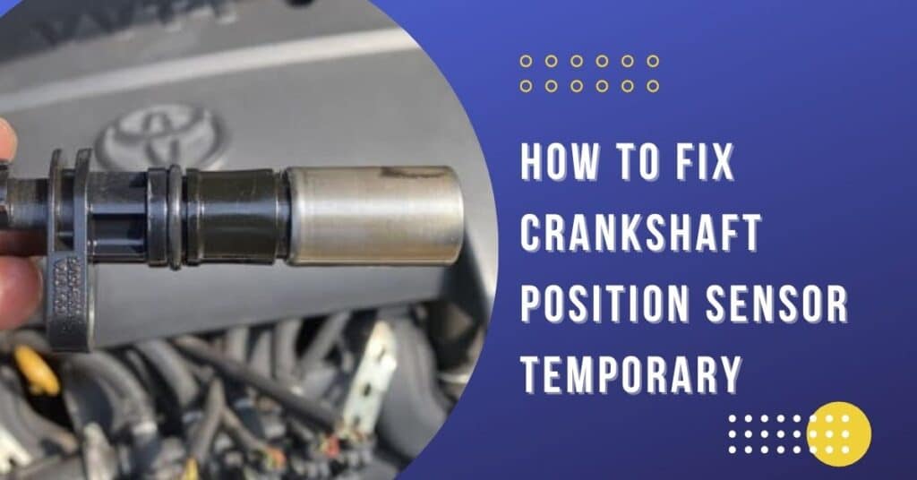
Do not repair a damaged sensor by gluing, cutting into the sensor body, bending its sensing tip, or modifying its mounting position. The sensor must maintain the correct relationship with the crankshaft trigger or reluctor. An incorrect air gap or damaged sensing end can prevent the system from producing a usable signal.
Source: autotoride.com
Repair the wiring when appropriate
A confirmed open, short, damaged conductor, or poor connection may be repairable without replacing the sensor.
Replace a failed sensor
If testing identifies an internal sensor failure, install the correct replacement part rather than attempting to rebuild the sensor.
Check related components
Inspect the connector, sensor mounting area, crankshaft trigger or reluctor, and related circuits before declaring the sensor defective.
How to Diagnose a Crankshaft Sensor Problem
Start with the least invasive checks. Read the diagnostic trouble codes, inspect the sensor and harness, confirm the connector is secure, and then perform electrical tests required by the vehicle manufacturer. Avoid replacing the sensor based on a code alone.
Before testing, identify whether your vehicle uses a two-wire magnetic sensor or a powered sensor with additional circuits. The correct test values and procedures differ. Applying an incorrect voltage or resistance test can lead to a false diagnosis or damage on some circuits.
A scan tool can provide useful information during cranking. On vehicles that report engine speed while the starter is turning, a missing or implausible RPM signal can provide an important clue. However, scan data must be interpreted with the vehicle’s service information and other test results.
Source: askcarmechanic.com
Step 1: Read the trouble codes
Use an OBD-II scanner to identify stored and pending codes. Record the codes before clearing anything.
Step 2: Inspect the sensor
Look for physical damage, contamination, loose mounting, damaged seals, or signs that the sensor has contacted a rotating component.
Step 3: Inspect the connector
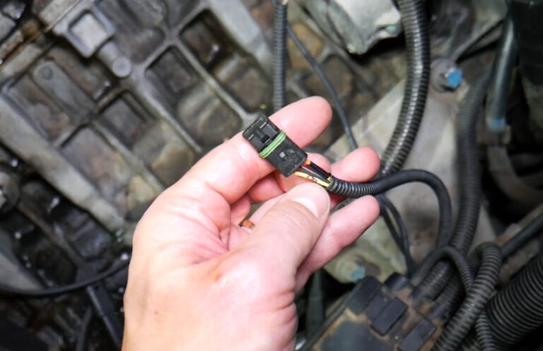
Check for bent terminals, corrosion, damaged locking tabs, moisture, loose terminal fit, and pulled wires.
Step 4: Inspect the harness
Follow the wiring away from the sensor and look for rubbing, melting, cuts, crushed sections, poor previous repairs, or contact with hot exhaust components.
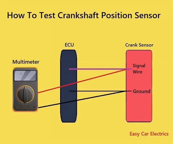
Step 5: Test the circuit
Use the manufacturer’s wiring diagram and test procedure to check power, ground, continuity, resistance, and signal as applicable.
Step 6: Compare the results
Replace the sensor only when the test results support sensor failure and other likely causes have been excluded.
Why a Trouble Code Does Not Prove the Sensor Is Bad
A diagnostic trouble code identifies a condition detected by the vehicle’s control system. It does not necessarily identify the failed physical component. A circuit code may result from a broken wire, short circuit, poor connection, damaged connector, power supply problem, or sensor failure.
For that reason, a useful diagnosis follows the circuit from the control module toward the sensor and checks the conditions specified by the manufacturer. This approach reduces unnecessary parts replacement.
Code
Shows what condition the computer detected.
Test
Determines which part of the system is actually causing the condition.
Repair
Addresses the confirmed cause instead of replacing parts based only on the code.
How to Repair Crankshaft Sensor Wiring
If testing confirms a wiring fault, repair the affected circuit according to the vehicle manufacturer’s wiring requirements. The repair must restore electrical continuity and protect the conductor from moisture, vibration, heat, and abrasion.
First disconnect the battery if the manufacturer’s procedure calls for it and identify the correct wires from the wiring diagram. Do not rely only on wire color because colors and circuit arrangements vary among vehicles. Trace the circuit from the CKP connector to the relevant control module or junction point.
For a damaged connector, a vehicle-specific replacement pigtail may be required. For a damaged wire, use an appropriate automotive-grade repair method and protect the finished repair from environmental exposure. Avoid twisting wires together and covering them with ordinary household tape.
After the repair, secure the harness in its original routing or an equivalent safe route. Keep it away from exhaust components, belts, pulleys, sharp edges, and other moving or hot parts. A wiring repair that works electrically but is poorly routed can fail again.
Source: drivenowautomotive.com
Use the wiring diagram
Identify each circuit by its function and terminal location rather than assuming the wire color or position.
Repair the correct section
Inspect both sides of the connector and the harness because the visible damage may not be the only fault.
Protect the repair
Use an automotive-appropriate repair method and restore insulation and mechanical protection.
Restore harness routing
Keep repaired wiring secured and away from heat, moving components, and sharp edges.
When a Connector Should Be Replaced
A connector may need replacement when terminals are corroded, loose, broken, pushed out of position, or unable to maintain reliable contact. Cleaning light contamination can sometimes restore a connection, but cleaning will not repair a terminal that has lost its mechanical tension or has significant corrosion damage.
Use the correct replacement connector or pigtail for the vehicle. Terminal position and locking features matter because a connector that appears to fit can still create an unreliable electrical connection.
Corroded terminals
Replace severely corroded terminals or the connector rather than relying on a temporary cleaning.
Loose terminals
A terminal that does not grip its mating terminal securely can cause an intermittent sensor signal.
Broken connector lock
A damaged locking mechanism can allow the connector to loosen from vibration.
How to Replace a Crankshaft Position Sensor
If testing confirms that the crankshaft position sensor has failed, replacement is usually more practical than attempting to repair the sensor itself. The exact procedure depends heavily on the vehicle. Some sensors are easy to reach from above, while others require removal or repositioning of nearby components.
Before beginning, obtain the correct replacement sensor and the vehicle-specific removal and installation procedure. Confirm whether the procedure requires a new O-ring, a particular installation lubricant, a specified torque, or a crankshaft position sensor relearn after installation.
Park the vehicle on a stable surface, switch the ignition off, and allow hot components to cool. If access requires lifting the vehicle, use equipment rated for the vehicle and support it correctly. Never rely on a jack alone while working underneath a vehicle.
Source: y-ic.com
1. Disconnect the battery if specified
Follow the manufacturer’s procedure for electrical isolation before disconnecting the sensor.
2. Locate the sensor
Use vehicle-specific service information to identify the CKP sensor and determine which components must be removed for access.
3. Disconnect the connector
Release the connector lock carefully and inspect the connector and terminals before removing the sensor.
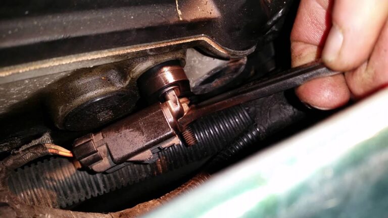
4. Remove the retaining fastener
Remove the sensor mounting bolt or fastener using the correct tool and avoid damaging nearby components.
5. Remove the old sensor
Gently twist or pull the sensor as directed by the service procedure. Do not force a stuck sensor in a way that could break it inside the engine.
6. Prepare the mounting area
Clean the sensor mounting surface as specified and prevent debris from entering the engine.
7. Install the new sensor
Install the correct sensor with the correct seal or O-ring and use the specified lubricant when required.
8. Tighten the fastener correctly
Use the vehicle-specific torque specification rather than guessing the tightening force.
9. Reconnect the wiring
Make sure the connector locks securely and route the harness away from heat and moving components.
10. Perform required relearn procedures
If the vehicle requires a crankshaft position sensor relearn, perform it with the appropriate scan tool and service procedure.
Why Correct Sensor Installation Matters
A crankshaft sensor must sit at the correct position relative to the crankshaft trigger. A sensor that is not fully seated, has the wrong dimensions, has a damaged O-ring, or is installed incorrectly can produce an unreliable signal or become damaged by contact with a rotating component.
Do not assume that every crankshaft sensor uses the same installation procedure. Some applications use a simple bolt-on sensor, while others require additional access work or a specific setup procedure.
Correct sensor
Verify the replacement part matches the vehicle application and engine.
Correct seal
Replace or lubricate the seal as required by the manufacturer’s procedure.
Correct torque
Use the specified torque because overtightening or undertightening can cause problems.
What to Do After Repairing or Replacing the Sensor
After the repair, inspect the connector and harness one more time. Confirm that every removed component is installed correctly and that no tools, fasteners, or loose wiring remain near belts, pulleys, fans, exhaust components, or other moving parts.
Reconnect the battery when the repair procedure calls for it. Start the engine and observe whether the original symptom has disappeared. If the engine does not start, do not immediately assume the new sensor is defective. Recheck the connector, wiring, installation position, fuse or power supply, and any other diagnostic conditions specified for the vehicle.
Use a scan tool to check current and pending codes after the repair. Some vehicles need a crankshaft position sensor variation or relearn procedure. Others learn the replacement sensor automatically. The vehicle-specific service procedure determines which situation applies.
A successful repair should be confirmed by normal starting and engine operation, absence of the original fault, and diagnostic results that are consistent with a repaired system. If the Check Engine Light returns, continue diagnosis instead of repeatedly replacing parts.
Source: 2carpros.com
Check the connector
Make sure the connector is fully seated and locked.
Check the wiring
Confirm the harness is secured and clear of heat and moving parts.
Scan again
Check for stored or returning diagnostic trouble codes after the repair.
Complete relearn if required
Follow the manufacturer’s procedure when the vehicle requires crankshaft position sensor calibration or relearning.
Common Mistakes to Avoid
The most common mistake is replacing the sensor without diagnosing the circuit. A new sensor cannot correct a broken wire, poor connector terminal, missing power supply, damaged ground, or mechanical problem affecting the sensor signal.
Another mistake is using generic specifications. Sensor resistance, voltage, waveform characteristics, mounting torque, and relearn requirements vary among vehicles. A value that is correct for one model may be wrong for another.
Avoid forcing a stuck sensor out of its mounting location. Some sensors can become stuck because of corrosion, oil contamination, or a hardened seal. Excessive force can break the sensor and make removal more difficult.
Do not ignore the possibility of a mechanical problem. A damaged crankshaft trigger, incorrect timing, excessive movement, or another engine fault can create a sensor-related symptom even when the sensor itself works correctly.
Source: autotoride.com
Replacing parts by code alone
A trouble code is a diagnostic clue, not automatic proof that the sensor has failed.
Guessing torque values
Always use the correct vehicle-specific specification.
Ignoring harness damage
Inspect the wiring near the sensor and along its complete accessible route.
Using the wrong sensor
Verify the sensor matches the exact vehicle, engine, and application.
Skipping required relearn procedures
Some vehicles require a scan-tool procedure after replacement, while others do not.
When to Stop and Use a Professional Repair Shop
A crankshaft sensor repair may be manageable for an experienced DIY mechanic when the sensor is accessible and the vehicle-specific procedure is straightforward. Professional help becomes more appropriate when diagnosis requires advanced electrical testing, difficult component removal, or specialized scan-tool procedures.
Stop the repair if the sensor breaks inside the engine, access requires extensive component removal that you cannot safely perform, or you cannot identify the correct wiring and test procedure. A damaged connector or harness can also require specialized terminal tools and wiring information.
If the vehicle stalls unexpectedly in traffic, loses power in a way that creates a hazard, or repeatedly fails to start, avoid relying on a temporary workaround. Arrange for safe transportation and diagnosis instead of continuing to operate a vehicle with an unresolved intermittent engine problem.
Source: y-ic.com
Difficult access
Professional service may be safer when major components must be removed to reach the sensor.
Advanced electrical diagnosis
A scope, specialized meter, wiring information, or other diagnostic equipment may be needed for difficult intermittent faults.
Broken sensor
A sensor that breaks during removal can require additional disassembly or specialized extraction.
Recurring fault
If the same fault returns after replacement, further diagnosis is needed rather than another replacement sensor.
Frequently Asked Questions
Q
Can a crankshaft position sensor be repaired?
The sensor itself is usually replaced rather than internally repaired. However, the problem can sometimes be repaired without replacing the sensor when the actual cause is damaged wiring, a poor connector, corrosion, or another external circuit fault.
Diagnosis should identify the failed component before replacement.
Q
Can I fix a crankshaft sensor wiring problem myself?
You can repair a wiring problem if you can correctly identify the circuit and use an appropriate automotive wiring repair method. The vehicle’s wiring diagram and service procedure should determine which terminals, wires, and test values apply.
If the wiring is difficult to access or the fault is intermittent, professional electrical diagnosis may be more appropriate.
Q
Will a bad crankshaft sensor prevent a car from starting?
It can. A complete or intermittent loss of the crankshaft position signal can prevent the engine computer from receiving the information it needs during starting.
However, many other faults can cause a no-start condition, so a no-start symptom alone does not prove that the crankshaft sensor is defective.
Q
Do you have to relearn a crankshaft sensor after replacing it?
It depends on the vehicle. Some vehicles require a crankshaft position sensor variation or relearn procedure after replacement, while others do not require a separate learning procedure.
Use the service information for the exact year, make, model, and engine rather than assuming that one procedure applies to every vehicle.
Q
Can a crankshaft sensor cause a car to stall while driving?
Yes, an intermittent or failing crankshaft position signal can contribute to engine stalling. The same symptom can also result from other electrical, fuel, ignition, or mechanical problems.
If the vehicle repeatedly stalls while driving, treat the condition as a safety concern and diagnose it before continuing normal road use.
Q
What codes are associated with crankshaft position sensor problems?
P0335 through P0339 are commonly associated with crankshaft position sensor or circuit conditions, but the exact interpretation depends on the vehicle and diagnostic strategy.
A code should be followed by circuit and component testing because wiring, connectors, mechanical timing, and other faults can produce similar diagnostic results.
✦ Wrapping Up
Conclusion
Learning how to repair a crankshaft sensor problem starts with diagnosis, not parts replacement. Inspect the sensor, connector, and wiring, read the diagnostic codes, and perform the correct electrical and signal tests for the specific vehicle. If the sensor is confirmed defective, replacement is usually the appropriate repair.
After installation, verify the connector and harness, use the correct fastener torque, complete any required relearn procedure, and scan the vehicle again. If the original problem remains, investigate wiring and related engine systems instead of assuming the replacement sensor is also bad.
💡 Key Takeaway
Before replacing a crankshaft sensor, confirm whether the fault is actually the sensor, its wiring, its connector, or another related engine problem, then follow the vehicle-specific repair and relearn procedure.
Ethan Brooks is an automotive writer at Auto News 7, covering car news, vehicle maintenance, new model updates, recalls, and practical buying guides. He focuses on clear, useful information that helps drivers understand their vehicles and make better ownership decisions.
Learn how to wire a crankshaft position sensor safely, identify sensor wires, connect 2-wire and 3-wire sensors, test circuits, and fix common wiring faults.
Learn how to fix a crankshaft position sensor with step-by-step diagnostics, testing, wiring checks, replacement tips, common symptoms, and troubleshooting advice for U.S. vehicle owners.
Learn how to remove a broken camshaft sensor safely and correctly. Follow this step-by-step guide to extract a stuck or broken camshaft position sensor without damaging the engine.
Learn when to replace a camshaft position sensor, the warning signs of failure, diagnostic tips, replacement timing, costs, and whether it is safe to keep driving.