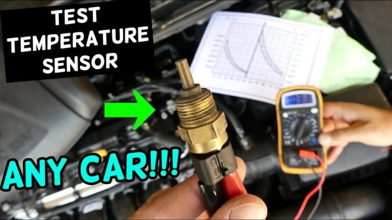
To troubleshoot a coolant temperature sensor, start with a cold-engine scan-tool reading, then check coolant level and sensor wiring, monitor the sensor signal as the engine warms, and compare resistance or voltage with the specifications for your exact vehicle. Do not replace the sensor solely because a trouble code is present.
For drivers and DIY mechanics in the United States, a faulty engine coolant temperature sensor can affect starting, fuel delivery, idle quality, emissions control, radiator-fan operation, and the temperature information displayed to the driver. The sensor is commonly called an ECT sensor and normally uses a thermistor whose electrical resistance changes with coolant temperature.
The most reliable diagnosis separates a sensor problem from a wiring fault, poor connector contact, low coolant level, trapped air, thermostat problem, or another cooling-system issue. A scan tool is the best starting point because it shows what temperature the engine computer is actually receiving rather than relying only on the dashboard gauge.
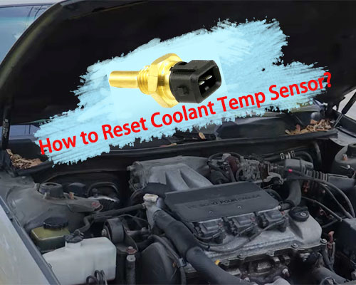
Source: utpaqp.edu.pe
What Does the Engine Coolant Temperature Sensor Do?
The engine coolant temperature sensor measures coolant temperature and sends an electrical signal to the engine control module. The module uses that information to adjust fuel delivery and ignition-related control strategies and, depending on the vehicle, to help control radiator fans and other systems.
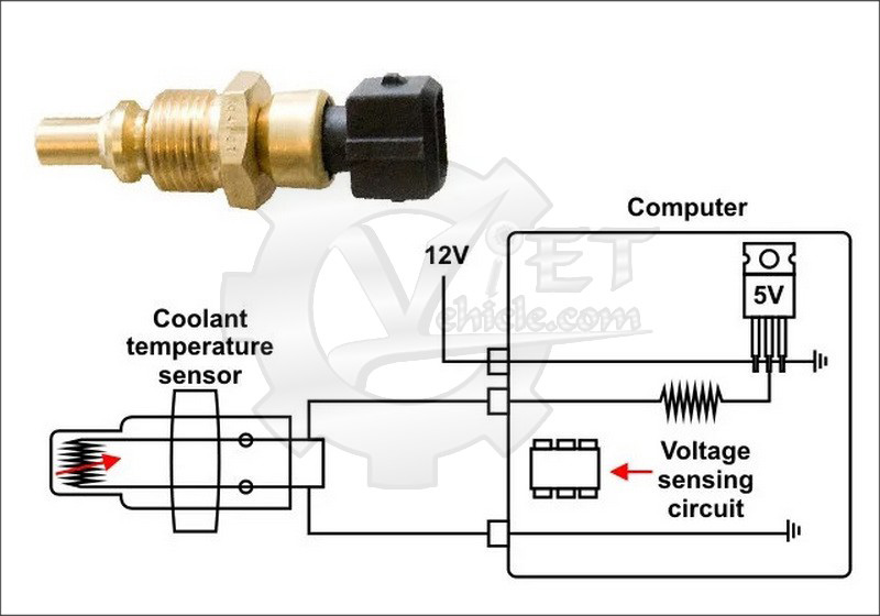
Most conventional ECT sensors use a negative temperature coefficient thermistor. Its resistance decreases as temperature increases. The engine computer interprets the resulting voltage as a temperature value. Because the computer evaluates the entire electrical circuit, a wiring or connector problem can look like a failed sensor.
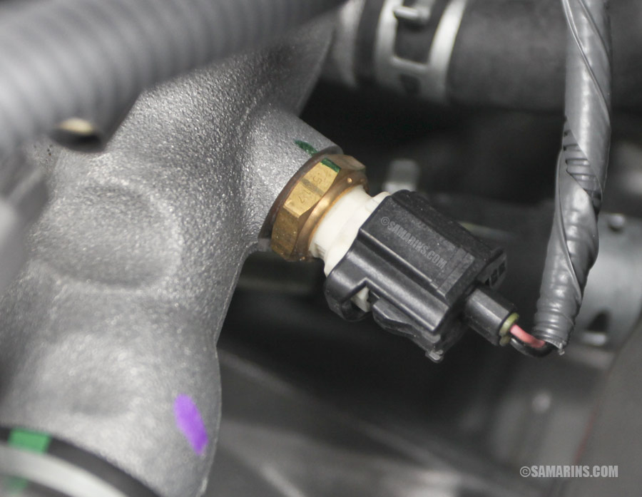
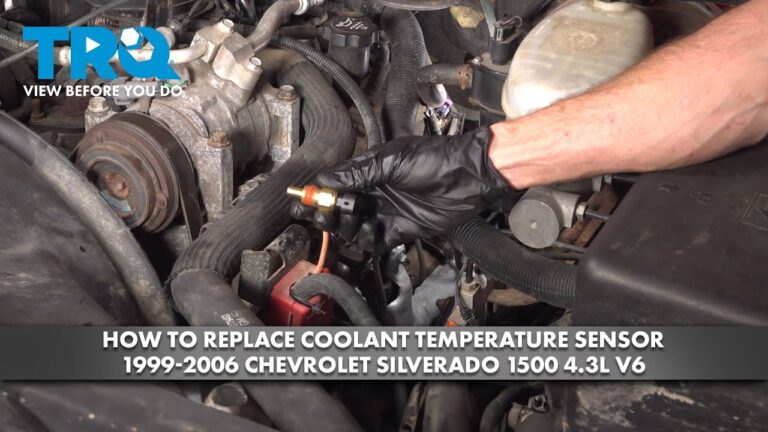
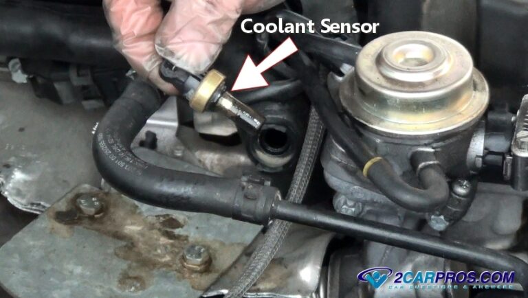
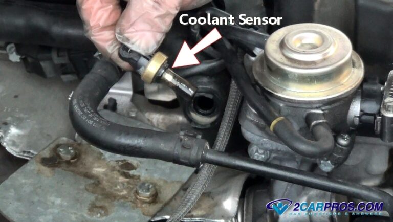
The exact sensor location varies by vehicle. It may be installed in the cylinder head, engine block, intake manifold, coolant outlet, thermostat housing, or another coolant passage. Some vehicles use more than one coolant-temperature sensor, so identify the correct component using the vehicle-specific service information.
Source: cfsensor.net
Cold engine
The ECT reading should generally be close to the actual ambient or engine temperature after the vehicle has been sitting long enough to cool completely.
Warming engine
The reported temperature should normally increase progressively as the engine warms rather than jumping randomly, becoming stuck, or dropping unexpectedly.
Hot engine
The scan-tool reading should remain plausible compared with the actual coolant temperature and the vehicle manufacturer’s operating specifications.
Common Signs of an ECT Sensor or Circuit Problem
Common symptoms include difficult starting, an unusually high or low idle, increased fuel consumption, poor drivability, an inaccurate temperature indication, radiator-fan behavior that does not match engine temperature, or an illuminated check-engine light. These symptoms are not specific enough to prove that the sensor itself has failed.
Temperature reading that does not make sense
An implausible cold-start temperature or a reading that suddenly changes without a corresponding change in engine temperature deserves circuit testing.
Poor cold starting
An incorrect temperature signal can cause the engine computer to calculate an inappropriate cold-start fuel strategy.
Cooling fan behavior
On vehicles that use ECT information for fan control, an incorrect signal can contribute to abnormal fan operation.
Start With the Safest and Most Useful Checks
Begin diagnosis with the vehicle parked safely and the engine completely cold. A cooling system can remain pressurized after shutdown, and opening a hot radiator or coolant reservoir can cause severe burns. Never remove a pressure cap or disconnect a coolant component while the system is hot.
Before testing the sensor itself, check the coolant level according to the vehicle manufacturer’s procedure and look for obvious leaks. Low coolant or trapped air can prevent the sensor from seeing representative coolant temperature and can create symptoms that resemble an electrical fault.
You will normally need a scan tool capable of displaying live data, a digital multimeter, appropriate back-probe leads, basic hand tools, the vehicle-specific wiring diagram, and the manufacturer’s sensor specifications. A thermometer can be useful when comparing actual coolant temperature with scan data.
Source: samarins.com
Work only on a cold cooling system
Allow sufficient cooling time before opening the system or removing the sensor.
Check coolant condition and level
Correct low coolant or an obvious cooling-system problem before interpreting temperature-sensor readings.
Keep hands away from moving components
During running-engine tests, stay clear of the radiator fan, belts, pulleys, and other moving or hot components.
Use vehicle-specific specifications
Do not use a generic resistance or voltage value as a universal pass/fail limit.
Tools You May Need
A basic diagnosis can often be performed with a scan tool and digital multimeter. More involved testing may require back-probe pins, a thermometer, wiring diagrams, a suitable sensor socket, and equipment for safely collecting or refilling coolant.
Scan tool
Use live data to observe ECT temperature, stored diagnostic trouble codes, and freeze-frame information when available.
Digital multimeter
Use it for voltage, resistance, continuity, and circuit checks as specified by the service procedure.
Vehicle service information
Use the correct terminal identification, resistance curve, voltage limits, wiring diagram, torque specification, and coolant procedure for the vehicle.
How to Troubleshoot a Coolant Temperature Sensor Step by Step
The most useful diagnostic order is to verify the reported temperature first, then inspect the circuit, measure the connected signal, and only afterward perform a sensor resistance test. This prevents a common mistake: replacing a sensor when the actual fault is in the connector or wiring.
The following sequence applies broadly to conventional ECT systems, but terminal locations, test values, and procedures differ among vehicles. Follow the factory service information whenever it provides a vehicle-specific test.
Source: detroitchinatown.org
Step 1: Scan for diagnostic trouble codes
Read stored and pending codes and save freeze-frame information before clearing anything. Codes in the P0115 through P0119 family commonly relate to ECT circuit or performance faults, but the exact diagnostic meaning and test strategy depend on the vehicle.
Step 2: Check the cold-engine temperature
After the vehicle has cooled completely, compare the ECT reading with ambient temperature or another appropriate temperature input. A large unexplained difference is a reason to investigate the sensor circuit before starting the engine.
Step 3: Watch the temperature during warm-up
Start the engine and monitor ECT live data. The value should generally rise in a believable and progressive manner as the engine warms. Sudden jumps, dropouts, or an implausible fixed value can indicate an intermittent circuit or sensor problem.
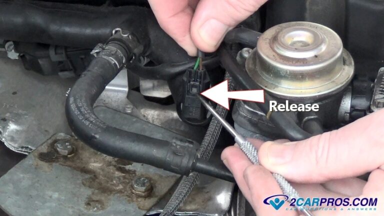
Step 4: Inspect the connector
Turn the ignition off and inspect the connector for corrosion, moisture, damaged locks, bent terminals, pushed-out terminals, poor terminal tension, or damaged wiring near the connector.
Step 5: Perform a wiggle test when appropriate
With the scan tool monitoring ECT data, gently move the connector and nearby harness without placing hands near moving components. A sudden temperature or voltage change can expose an intermittent connection.
Step 6: Check the sensor circuit voltage
With the connector disconnected and the ignition in the position specified by the service procedure, measure the appropriate reference and ground circuits. Many ECT systems use approximately a 5-volt reference, but the exact circuit design must be confirmed for the vehicle.
Step 7: Test wiring continuity and shorts
If the sensor and connector appear sound but the signal remains incorrect, use the wiring diagram to check for open circuits, excessive resistance, shorts to ground, shorts to voltage, and poor terminal connections.
Step 8: Test sensor resistance if required
Disconnect the sensor and measure its resistance at a known temperature. Compare the result with the manufacturer’s temperature-versus-resistance specification. Because ECT thermistors normally have lower resistance at higher temperatures, the reading should change predictably as temperature changes.
How to Interpret the Scan Tool Reading
A cold-soak comparison is one of the fastest ways to identify an implausible temperature signal. If the engine has been sitting overnight, the coolant temperature should generally be near the surrounding temperature. After startup, the ECT value should change as the engine warms.
Some vehicles use specific default values when the ECT circuit is open or shorted. A scan tool may display an extreme temperature such as approximately -40 degrees when a circuit is open, but this behavior is not a universal diagnostic rule. Use the vehicle’s service information to interpret the actual reading.
Reading too cold
Consider an open circuit, excessive resistance, poor terminal contact, a faulty sensor, or another circuit problem. Also verify that the engine is actually warming normally.
Reading too hot
Consider a shorted signal circuit, sensor fault, connector problem, or another electrical condition. Confirm actual coolant temperature before drawing a conclusion.
Reading jumps or drops
An intermittent connector, damaged wire, poor terminal tension, or failing sensor can cause abrupt changes.
How to Test the ECT Sensor With a Multimeter
If the service information calls for resistance testing, disconnect the sensor before measuring resistance. Record the coolant or sensor temperature at the time of measurement and compare the resistance with the exact specification for that sensor. Do not substitute a generic resistance chart for the manufacturer’s data.
A two-point test is more useful than a single measurement because it checks whether the thermistor changes resistance as temperature changes. A sensor can appear reasonable at one temperature while behaving incorrectly at another.
Measure cold
Record sensor temperature and resistance, then compare both with the specified values.
Measure warm
If the service procedure permits an off-vehicle temperature test, use controlled water temperature and a thermometer while monitoring resistance.
Do not guess specifications
ECT resistance curves vary considerably among sensors, so an ohmmeter reading is meaningful only when compared with the correct specification.
Use Symptoms and Trouble Codes to Narrow the Cause
Symptoms and diagnostic trouble codes are clues, not automatic proof that the ECT sensor needs replacement. The same complaint can result from the sensor, connector, wiring, thermostat, coolant level, air in the system, or another cooling-system component.
For example, a code indicating an ECT circuit high or low input points toward an electrical condition, while a code associated with temperature range or performance may require checking how the engine warms as well as the sensor circuit.
Source: hitchesguide.com
P0115
Generally associated with an engine coolant temperature sensor circuit malfunction. Diagnose the complete circuit rather than replacing the sensor automatically.
P0116
Generally associated with ECT sensor range or performance. Check whether the temperature signal follows a plausible warm-up pattern and whether the engine reaches its expected operating temperature.
P0117
Generally associated with ECT circuit low input. Check for a shorted signal circuit, sensor fault, connector problem, or other condition identified by the vehicle-specific diagnostic procedure.
P0118
Generally associated with ECT circuit high input. Check for an open circuit, excessive resistance, disconnected sensor, connector fault, or other causes listed by the manufacturer.
P0119
Generally associated with an intermittent ECT circuit. Pay particular attention to wiring movement, connector tension, corrosion, and signal dropouts.
When the Thermostat May Be the Real Problem
An engine that warms too slowly or fails to reach its expected operating temperature does not automatically have a bad ECT sensor. A thermostat that remains open or otherwise operates incorrectly can produce a genuine low-temperature condition while the sensor reports it accurately.
To distinguish the two, compare the scan-tool ECT value with the actual coolant temperature and observe the warm-up pattern. If the sensor value is plausible but the engine does not reach the specified operating temperature, investigate the thermostat and the rest of the cooling system.
Sensor reading plausible
If scan data agrees with actual coolant temperature, the sensor may be doing its job even when the engine is running cooler than expected.
Temperature rises abnormally slowly
Consider thermostat operation, coolant flow, ambient conditions, and other cooling-system factors before replacing the ECT sensor.
Temperature does not change logically
A circuit or sensor problem becomes more likely when the reported temperature does not correspond with actual engine conditions.
Coolant Temperature Sensor Troubleshooting Decision Table
Use this table to decide what to inspect next. The exact pass/fail values must come from the service information for the vehicle being diagnosed.
Source: storage.googleapis.com
Cold ECT reading is close to ambient temperature
Proceed to warm-up monitoring. This suggests the initial temperature signal is plausible but does not prove the sensor is accurate at all temperatures.
Cold ECT reading is far from ambient
Inspect the connector and wiring, check the reference and ground circuits, and test the sensor according to the manufacturer’s procedure.
ECT changes smoothly during warm-up
The sensor circuit is behaving plausibly. If a temperature-related fault remains, compare actual coolant temperature and investigate the thermostat or cooling system.
ECT jumps, freezes, or suddenly drops
Inspect for intermittent wiring, poor terminal tension, corrosion, connector movement, or a failing sensor.
Reference voltage is missing
Do not replace the sensor yet. Trace the reference, ground, wiring, and control-module circuit according to the vehicle-specific diagnostic procedure.
Sensor resistance is outside specification
If temperature is known and the correct resistance specification has been used, the sensor is a likely fault. Verify the rest of the circuit before replacement.
Sensor resistance is correct but scan data is wrong
Focus on the installed circuit, connector, wiring, reference, ground, and module-side connections because a bench resistance test cannot evaluate those components.
Why a Good Sensor Can Still Produce a Bad Reading
The engine computer does not simply read the sensor’s resistance in isolation. It interprets the voltage produced by the sensor and its associated circuit. Added resistance, poor terminal contact, corrosion, a short, or wiring damage can therefore change the temperature reported by the computer even when the sensor itself tests normally on a bench.
Connector resistance
Corrosion or poor terminal tension can add unwanted resistance and alter the signal.
Open or damaged wire
A broken conductor can cause an implausible or default temperature value.
Short circuit
A signal wire contacting ground or another circuit can force the voltage outside its expected range.
Common Mistakes When Troubleshooting an ECT Sensor
The most common diagnostic mistake is treating the trouble code as a parts-ordering instruction. An ECT code identifies a monitored condition; it does not necessarily identify the failed component. A disciplined diagnosis checks the complete signal path.
Another mistake is relying on a generic resistance value found online. Different ECT sensors have different resistance curves, and even similar-looking sensors can have different electrical characteristics. Always use the specification for the exact vehicle and sensor application.
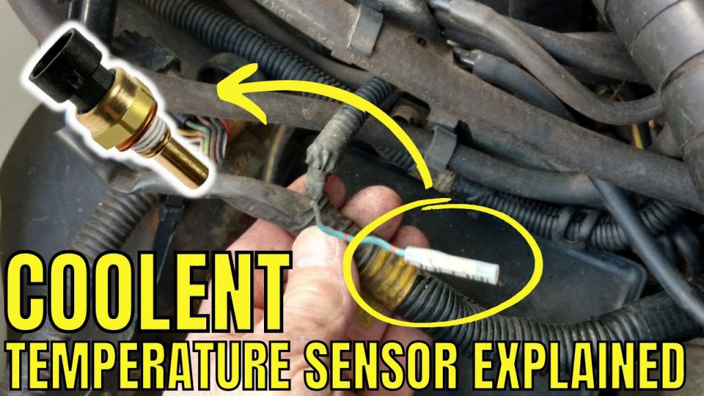
Source: www.youtube.com > Little Hollow Homestead
Replacing the sensor immediately
A corroded connector or damaged wire can create the same fault. Inspect the complete circuit first.
Testing a hot cooling system
Removing a sensor or opening the cooling system while hot can expose you to pressurized coolant and serious burns.
Using the dashboard gauge as the only test
The dashboard gauge may be filtered, simplified, or controlled separately from the exact ECT data used by the engine computer. Scan data provides more diagnostic information.
Ignoring coolant level
Low coolant can prevent the sensor from accurately sensing coolant temperature and may indicate a separate leak that needs attention.
Probing terminals incorrectly
Improper probing can spread terminals or damage connectors. Use suitable back-probe equipment and follow the service procedure.
Ignoring air after sensor replacement
Some cooling systems require a specific bleeding or air-removal procedure. Trapped air around the sensor can cause misleading readings.
When DIY Troubleshooting Should Stop
Stop DIY work if the engine is overheating, coolant is rapidly escaping, the cooling system remains pressurized, electrical testing requires procedures you cannot perform safely, or access requires removal of components beyond your skill level. A professional technician should handle diagnosis when the consequences of an incorrect repair could damage the engine or expose you to hot coolant or moving components.
Overheating
Do not continue driving an overheating vehicle simply because the temperature sensor is suspected.
Major coolant leak
Repair the cooling-system problem before assuming an electrical sensor fault is the primary cause.
Unclear wiring diagnosis
Use professional diagnostic help rather than applying voltage to an unknown circuit or probing control-module terminals incorrectly.
What to Do After Finding the Fault
Once testing identifies the cause, repair the specific fault rather than replacing unrelated components. A failed sensor should be replaced with the correct application and installed according to the manufacturer’s sealing and torque requirements. A wiring fault should be repaired using an appropriate automotive repair method, and damaged terminals or connectors should be restored correctly.
After the repair, clear codes only after recording the original information. Recheck the ECT value from a cold start, monitor the temperature through warm-up, confirm that the reading remains plausible, and check for coolant leaks. If coolant was drained, follow the vehicle-specific refill and air-bleeding procedure.
A successful repair should eliminate the original abnormal reading or symptom, prevent the trouble code from returning under the same conditions, and produce believable ECT data during cold start and warm-up. If the code returns, use the new freeze-frame information and repeat the circuit diagnosis rather than automatically installing another sensor.
Source: fity.club
After a sensor replacement
Verify connector engagement, correct sealing, coolant level, air removal, leaks, and live temperature data.
After a wiring repair
Confirm circuit continuity and proper signal behavior before considering the repair complete.
After clearing a code
Use a suitable drive cycle or verification procedure specified for the vehicle and confirm that the fault does not return.
When the New Sensor Still Reads Wrong
If a replacement sensor produces the same incorrect reading, stop replacing parts and return to the circuit diagnosis. Verify that the replacement sensor is correct for the application, that the connector and terminals are sound, that the reference and ground circuits are correct, and that the cooling system has been properly refilled and purged of air.
If the electrical circuit and sensor test correctly but the engine temperature itself is abnormal, investigate the thermostat, coolant circulation, cooling fan system, radiator, water pump, and other cooling-system components as appropriate for the vehicle.
Wrong replacement part
A sensor can physically fit while having the wrong resistance curve or sealing arrangement.
Air trapped in the cooling system
Air around the sensor can prevent representative coolant contact and distort the reported temperature.
Underlying cooling-system problem
A functioning sensor can correctly report an engine that is genuinely running too hot or too cold.
Frequently Asked Questions
Q
How do I know if my coolant temperature sensor is bad?
Do not rely on symptoms alone. Compare the cold-engine ECT reading with ambient temperature, monitor the signal as the engine warms, inspect the connector and wiring, and compare sensor resistance or voltage with the exact vehicle specification. A sensor is more likely to be faulty when the circuit is sound but the sensor consistently fails its specified test.
Q
Can a bad coolant temperature sensor cause a check engine light?
Yes. The engine computer can set ECT-related diagnostic trouble codes when the signal is outside its expected range, changes implausibly, or behaves intermittently. However, the code can result from wiring, connector, or circuit faults rather than the sensor itself.
Q
What should a coolant temperature sensor read when the engine is cold?
After the vehicle has cooled completely, the ECT reading should generally be close to ambient temperature. The exact acceptable range depends on the vehicle and diagnostic system. A large unexplained difference is a useful reason to inspect the ECT circuit.
Q
Can low coolant cause a coolant temperature sensor code?
Low coolant can cause inaccurate temperature information because the sensor may not remain properly immersed in coolant. It can also create engine-temperature symptoms that resemble a sensor fault. Check coolant level and investigate leaks before condemning the sensor.
Q
Can a thermostat cause the same symptoms as a bad ECT sensor?
Yes. A thermostat that opens too early or fails to regulate coolant flow correctly can cause an engine to warm too slowly or operate outside its expected temperature range. If scan data agrees with actual coolant temperature, investigate the thermostat and cooling system instead of automatically replacing the sensor.
Q
Should I replace the coolant temperature sensor when I get P0117 or P0118?
Not automatically. These codes generally indicate an ECT circuit signal problem, but the underlying cause can be the sensor, connector, wiring, or another part of the circuit. Follow the vehicle-specific diagnostic procedure before replacing the component.
✦ Wrapping Up
Conclusion
The most effective way to troubleshoot a coolant temperature sensor is to diagnose the complete circuit rather than assuming the sensor is defective. Start with a cold-engine scan, verify coolant level and actual temperature, monitor ECT data through warm-up, inspect the connector and wiring, and then perform voltage or resistance tests using the vehicle-specific specifications.
If the sensor fails its specified test after the wiring and connector have been verified, replacement is reasonable. If the sensor tests correctly, continue investigating the circuit, thermostat, coolant level, trapped air, and other cooling-system components. This approach reduces unnecessary parts replacement and provides a more reliable diagnosis.
💡 Key Takeaway
Start with the engine cold: scan the ECT value, compare it with ambient temperature, inspect the connector and wiring, and monitor the temperature as the engine warms. Use the exact factory specifications before condemning or replacing the sensor.
Ethan Brooks is an automotive writer at Auto News 7, covering car news, vehicle maintenance, new model updates, recalls, and practical buying guides. He focuses on clear, useful information that helps drivers understand their vehicles and make better ownership decisions.
Learn how to remove a coolant temperature sensor safely. Follow this step-by-step guide for locating the sensor, disconnecting the wiring, draining coolant, removing the sensor, and checking for leaks.
Learn how to reset a coolant temperature sensor on a Chevy Silverado, clear related trouble codes, verify sensor operation, and avoid common diagnostic mistakes.
Learn how to test a Ford coolant temperature sensor with a multimeter and scan tool. Check resistance, voltage, wiring, sensor response, and common faults safely.
Learn how to check an engine coolant temperature sensor with a multimeter or OBD-II scanner. Follow safe testing steps, resistance checks, symptoms, and troubleshooting tips.
Learn how to replace a coolant temperature sensor safely, including tools, sensor removal, installation, coolant refill, bleeding, testing, and common mistakes.
Learn how to test a coolant temperature sensor with a multimeter or scan tool. Follow safe steps to check resistance, voltage, wiring, and sensor accuracy.