You can test most engine coolant temperature sensors with a digital multimeter by measuring resistance and comparing the result with the vehicle manufacturer’s specifications. You can also use an OBD-II scan tool to check whether the sensor reports a believable temperature as the engine warms up.
For drivers and DIY mechanics in the United States, a coolant temperature sensor is an important part of modern engine management. The engine coolant temperature, or ECT, sensor tells the vehicle’s powertrain control module how warm the engine is. That information can influence fuel delivery, ignition strategy, transmission operation, emissions controls, and cooling-system functions.
The most reliable way to diagnose an ECT sensor is not to replace it simply because a Check Engine light or temperature problem appears. First inspect the connector, wiring, coolant level, and sensor data. Then test the sensor itself against the specifications for the exact year, make, model, and engine. Most ECT sensors are negative-temperature-coefficient thermistors, meaning their resistance generally decreases as temperature increases, but the correct resistance values vary substantially by vehicle.
Source: storage.googleapis.com
What Is an Engine Coolant Temperature Sensor?
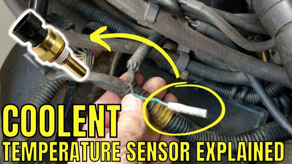
The engine coolant temperature sensor measures coolant temperature and sends an electrical signal to the vehicle’s engine computer. On many modern vehicles, the sensor is a two-wire thermistor supplied by a reference voltage from the powertrain control module. The sensor’s changing resistance alters the signal seen by the computer.
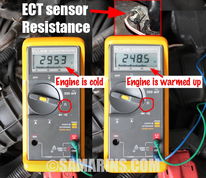
Most modern ECT sensors use a negative temperature coefficient design. In practical terms, resistance is higher when the sensor is cold and lower when it becomes hotter. The exact resistance curve differs between vehicles, so a generic resistance number should not be used as a pass-or-fail specification.
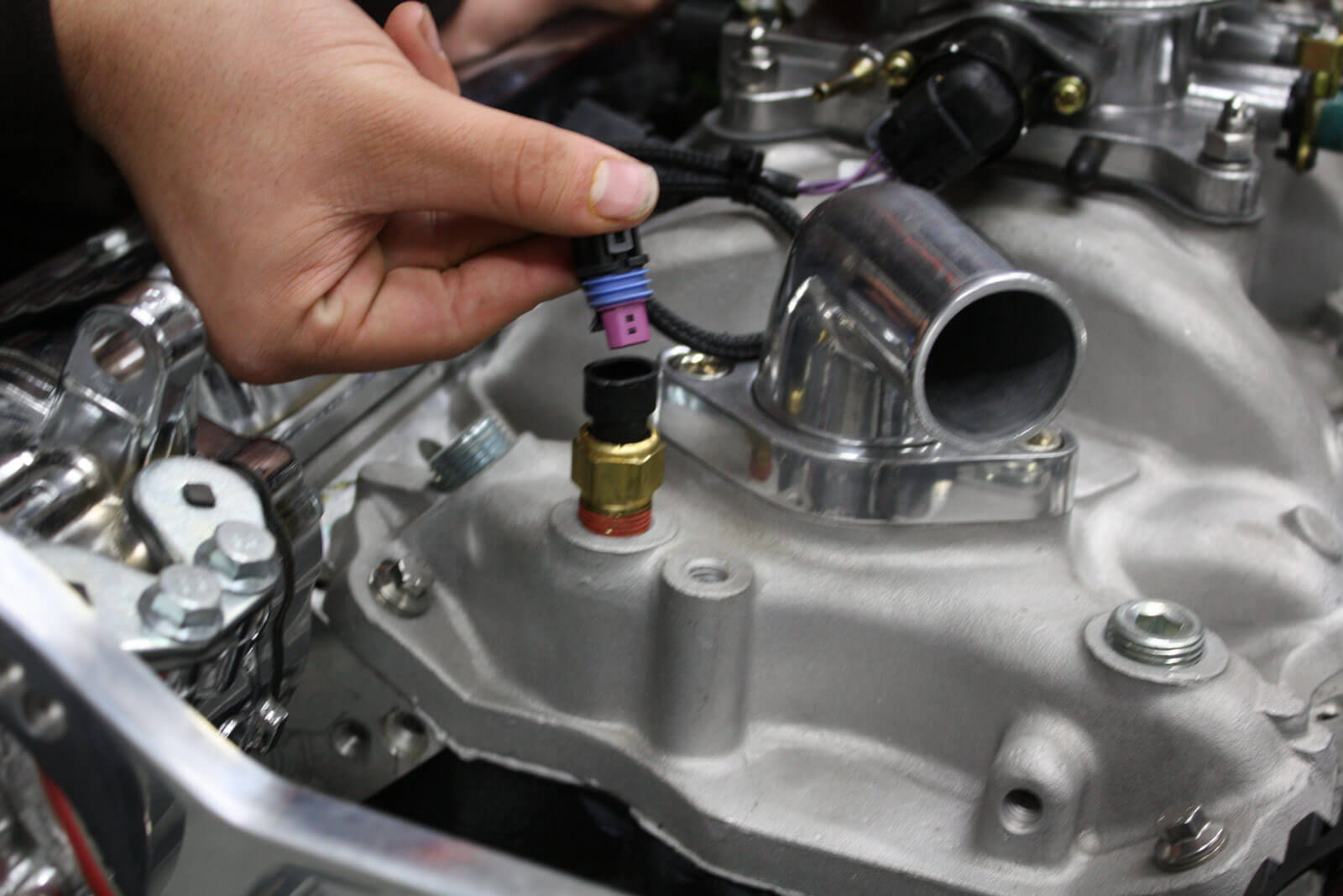
The ECT sensor is commonly installed in a coolant passage near the thermostat housing, cylinder head, intake manifold, or another location where its sensing element is exposed to engine coolant. Some vehicles use more than one coolant temperature sensor or use separate temperature-sending circuits for other functions.
Source: narodnatribuna.info
ECT sensor
Usually supplies engine-control temperature information to the PCM or ECM.
Temperature sender
On some vehicles, a separate sender supplies the dashboard temperature gauge or warning system.
Thermistor
A temperature-sensitive resistor whose electrical resistance changes as temperature changes.
What Does a Bad Coolant Temperature Sensor Cause?
A faulty or inaccurate ECT signal can contribute to hard starting, poor idle quality, excessive fuel consumption, incorrect emissions-control operation, cooling-fan problems, or an inaccurate temperature indication. Some vehicles may also set an OBD-II diagnostic trouble code such as P0115, P0116, P0117, P0118, or P0119.
These symptoms are not proof that the sensor is defective. A thermostat that is stuck open, low coolant, an electrical open or short, corrosion at the connector, or damaged wiring can create similar symptoms.
Common diagnostic clue
The scan-tool ECT reading is implausibly hot or cold compared with actual engine conditions.
Another clue
The ECT value does not change smoothly as the engine warms.
Important exception
An engine that genuinely stays too cool can indicate a thermostat problem rather than a failed temperature sensor.
What You Need Before Testing the Sensor
Gather the correct service information before measuring resistance. The factory repair manual or reliable vehicle-specific service information should provide the sensor’s resistance or voltage specifications, connector pin identification, test conditions, and any special procedures.
For a basic test, you will usually need a digital multimeter and, if available, an OBD-II scan tool that can display live engine coolant temperature data. Basic hand tools may be necessary to access or remove the sensor. Keep safety equipment available, including gloves and eye protection.
Do not start by removing the sensor. A scan-tool check and visual inspection can often identify an electrical or data problem without opening the cooling system.
Source: storage.googleapis.com
Digital multimeter
Used to measure resistance and, where appropriate, voltage.
OBD-II scan tool
Useful for reading live ECT data and diagnostic trouble codes on OBD-II-equipped vehicles.
Vehicle-specific specifications
Required to determine the correct resistance, voltage, connector pins, and test conditions.
Safety equipment
Use eye protection and gloves, and avoid contact with hot or pressurized coolant.
Safety Before You Touch the Cooling System
Work on the sensor with the engine cold unless the vehicle manufacturer’s diagnostic procedure specifically requires another condition. Never remove a radiator cap or open a pressurized cooling-system component while the engine is hot. Hot coolant can erupt under pressure and cause severe burns.
Keep hands, clothing, and test leads away from belts, fans, pulleys, and other moving components when the engine is running. Electric cooling fans can also start automatically even when the engine appears to be off.
Cold engine
The safest starting point for inspection and sensor removal is a fully cooled engine.
Electrical safety
Do not short connector terminals together with unsuitable tools or test leads.
How to Test a Coolant Temperature Sensor With an OBD-II Scan Tool
A scan tool is often the quickest first test because it lets you evaluate the sensor without removing it. The goal is to determine whether the reported coolant temperature is plausible and whether it changes normally as the engine warms.
Start with the engine completely cold. Connect the scan tool to the vehicle’s diagnostic connector and open the live-data screen that displays engine coolant temperature. Compare the ECT value with the ambient temperature or intake-air temperature reading. On a cold engine that has been sitting long enough to equalize, the readings should be reasonably close rather than showing an obviously extreme temperature.
Start the engine and monitor the ECT value. A functioning sensor circuit should normally show a progressive change as coolant temperature rises. A reading that remains fixed, jumps abruptly, or reports an implausible temperature can indicate a sensor, connector, wiring, or related control-system problem.
If the scan data looks reasonable but the engine takes unusually long to reach operating temperature, investigate the thermostat and cooling system instead of automatically replacing the ECT sensor.
Source: www.youtube.com > TA Automotive technology
Cold-engine comparison
Compare ECT with ambient or intake-air temperature before startup.
Warm-up behavior
Watch for a logical, progressive temperature increase as the engine warms.
Intermittent faults
If the reading suddenly jumps while the harness or connector is disturbed, inspect the wiring and terminals.
Diagnostic codes
Codes in the P0115 through P0119 range can point toward ECT circuit problems, but the code alone does not identify the failed component.
What the Scan Tool Results Mean
An implausibly high temperature on a cold engine can point toward an electrical short or an internally shorted sensor. An implausibly low temperature can indicate an open circuit, poor connection, or another wiring problem. Exact diagnostic logic varies by vehicle.
A normal-looking cold reading followed by erratic jumps during warm-up can indicate an intermittent sensor or connector problem. A normal sensor reading combined with a genuine overheating condition requires diagnosis of the cooling system rather than assuming the ECT sensor is responsible.
Reading changes normally
The sensor circuit is behaving plausibly, so investigate other causes if symptoms remain.
Reading never changes
Check the sensor, connector, wiring, and reference or ground circuits.
Reading is extreme
Inspect for an open, short, damaged wiring, poor connection, or sensor failure.
How to Test a Coolant Temperature Sensor With a Multimeter
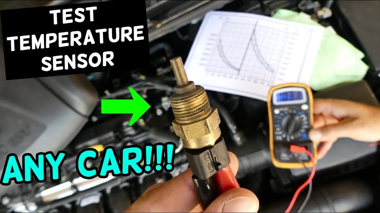
A multimeter can test the sensor’s resistance directly. This is one of the most useful DIY checks when the vehicle manufacturer provides a resistance-versus-temperature specification.
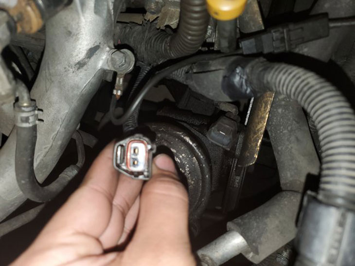
Allow the engine to cool completely before removing the electrical connector or sensor. Identify the correct sensor and connector using the vehicle’s service information. Disconnect the sensor connector without pulling on the wiring.
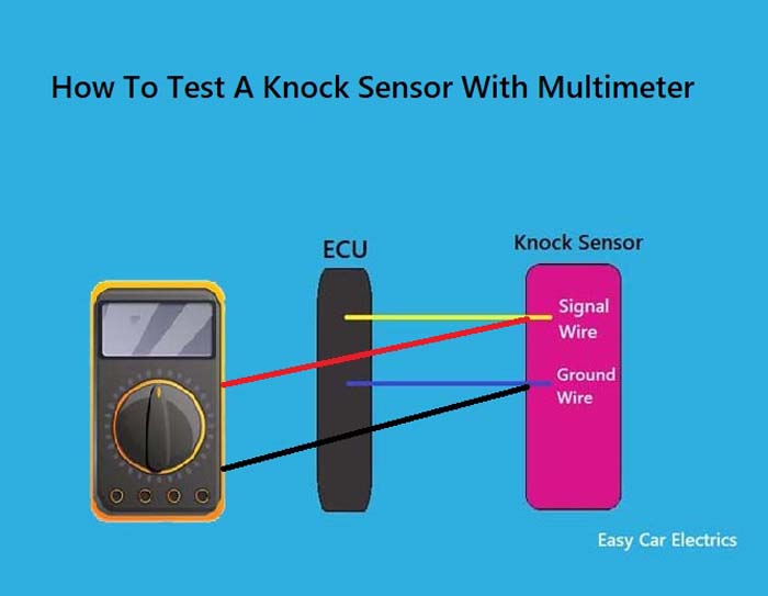
Set the digital multimeter to the resistance or ohms setting. With the sensor disconnected, place the meter probes across the appropriate sensor terminals. Record the resistance at the known test temperature and compare it with the manufacturer’s specification.
If the procedure requires testing at more than one temperature, measure the resistance at each specified temperature. For a typical NTC sensor, the resistance should decrease as temperature increases. The readings should follow the specified resistance curve rather than merely showing some change.
A sensor that is internally open, internally shorted, or substantially outside the manufacturer’s specified range is defective. If the resistance is within specification, continue diagnosing the connector, wiring, reference circuit, ground circuit, coolant level, thermostat, and PCM rather than replacing the sensor automatically.
Source: storage.googleapis.com
Step 1: Cool the engine
Begin with a safe, cooled engine unless the factory procedure specifies otherwise.
Step 2: Disconnect the sensor
Remove the electrical connector carefully and identify the correct sensor terminals.
Step 3: Measure resistance
Place the multimeter probes across the specified sensor terminals.
Step 4: Compare with specifications
Use the exact resistance-versus-temperature values for your vehicle.
Step 5: Check the trend
For a typical NTC sensor, resistance should fall as temperature rises.
Why You Should Not Use a Generic Resistance Chart
ECT resistance values vary significantly among manufacturers and sensor designs. Two sensors can both be healthy while showing very different resistance at the same temperature. For that reason, a generic value should be treated only as an illustration of thermistor behavior, not as a diagnostic specification.
For example, published automotive diagnostic information shows that one sensor family can have resistance in the thousands of ohms at cold temperatures while another can have a substantially different value. The correct pass-or-fail decision must come from the specification for the exact vehicle and sensor.
Correct approach
Match the measured resistance to the factory temperature and resistance specification.
Incorrect approach
Declaring a sensor good or bad because it matches a resistance value found for a different vehicle.
How to Check Coolant Temperature Sensor Wiring and Voltage
If the sensor’s resistance is within specification but the scan-tool reading is wrong, test the circuit before replacing parts. A two-wire ECT circuit commonly uses a reference voltage and a return path through the sensor, but the exact circuit design and test procedure depend on the vehicle.
Start with a visual inspection. Look for broken insulation, corrosion, loose terminals, damaged connector locks, coolant contamination, or wiring that has been pulled tight against the engine. A connector can look connected while still having poor terminal contact.
With the sensor disconnected and the ignition in the required test position, use the vehicle’s wiring diagram to identify the reference and return circuits. Measure only as specified by the service procedure. Do not assume every vehicle uses the same terminal arrangement or reference voltage.
If the sensor tests correctly but the signal reaching the control module is incorrect, check continuity, unwanted resistance, shorts to ground or power, and connector condition. Some faults may require back-probing or manufacturer-specific diagnostic equipment, so do not substitute a generic wiring test for the factory procedure.
Source: exokeeuil.blob.core.windows.net
Inspect first
Look for corrosion, broken wires, loose terminals, chafing, and damaged connector housings.
Verify circuit identification
Use the exact wiring diagram for the vehicle before measuring voltage or continuity.
Check the complete circuit
A good sensor cannot produce a correct signal if its reference, ground, signal, or return circuit is damaged.
What Does a 5-Volt Reference Tell You?
Many modern ECT circuits use a voltage reference supplied by the engine computer. The sensor changes the circuit’s electrical behavior according to temperature, allowing the computer to calculate coolant temperature. A missing reference voltage can therefore make a good sensor appear faulty.
Do not automatically condemn the PCM if the reference voltage is missing. A shorted sensor or another sensor sharing the same reference circuit can sometimes affect the voltage. Vehicle-specific diagnostic procedures should be followed before replacing a control module.
Reference present
This supports the integrity of one part of the circuit but does not prove the sensor is good.
Reference missing
Investigate wiring, shared reference circuits, connectors, and the control module according to the service procedure.
How to Tell Whether the Sensor or Thermostat Is the Problem
A coolant temperature complaint does not always mean the ECT sensor has failed. The sensor measures temperature; it does not create engine temperature. If the engine is genuinely running too cold or too hot, the cooling system itself must also be evaluated.
If scan-tool ECT data starts near ambient temperature and rises smoothly but the engine never reaches its expected operating temperature, a thermostat that is stuck open or another cooling-system problem may be more likely than a bad sensor.
Conversely, if the reported ECT temperature is obviously impossible, remains fixed, or changes abruptly while actual engine conditions do not, the sensor circuit deserves closer attention.
Low coolant can also affect sensor accuracy because the sensing element needs appropriate contact with coolant. Check the coolant level and investigate leaks using the vehicle manufacturer’s procedure.
Source: www.youtube.com > Dr. Cool
Sensor likely suspect
The electrical resistance or signal is outside specification, or the reading is implausible despite a sound circuit.
Thermostat likely suspect
The sensor reports a believable temperature but the engine takes too long to warm or remains below its expected operating temperature.
Cooling-system problem
Actual overheating, low coolant, leaks, fan problems, or restricted coolant flow require broader cooling-system diagnosis.
A Simple Diagnostic Decision Table
Use the following logic as a starting point rather than a substitute for the vehicle’s factory diagnostic procedure.
Cold ECT matches ambient temperature and rises smoothly
The ECT circuit appears to be functioning. Investigate other causes of the vehicle symptom.
Cold ECT is extremely high or extremely low
Inspect the sensor, connector, wiring, and circuit for an open or short.
ECT stays nearly unchanged during warm-up
Check the sensor and circuit, then consider whether the engine is actually changing temperature.
ECT behaves normally but engine stays cold
Investigate the thermostat and cooling system.
Sensor resistance is out of specification
Replace the sensor using the correct part and installation procedure.
Common Mistakes When Testing an ECT Sensor
The most common diagnostic mistake is replacing the sensor based solely on a Check Engine light, a trouble code, or a temperature-gauge symptom. An ECT-related code identifies a circuit or performance condition; it does not always identify the failed part.
Another mistake is using resistance specifications from another vehicle. Thermistor curves are application-specific, so the test must use the correct service information.
Avoid testing a sensor immediately after shutting off a hot engine unless the manufacturer’s procedure explicitly requires it. Heat soak can make the measured temperature different from the temperature you expect, and opening the cooling system can expose you to pressurized coolant.
Finally, do not overlook wiring. Corroded terminals, damaged insulation, loose connectors, and intermittent connections can mimic a defective sensor.
Source: YouTube > Auto Repair Guys
Mistake: replacing parts from a code alone
Use the diagnostic code as a starting point and verify the circuit and sensor.
Mistake: using generic resistance values
Always use specifications for the exact vehicle and engine.
Mistake: ignoring coolant level
Low coolant can interfere with temperature measurement and can indicate a separate cooling-system problem.
Mistake: overlooking the connector
Poor terminal contact or corrosion can create an intermittent or incorrect sensor signal.
Mistake: working around hot coolant
Allow the system to cool before opening or removing components unless a documented service procedure says otherwise.
When Should You Stop DIY Testing?
Stop and seek qualified repair assistance if the vehicle is overheating, coolant is escaping under pressure, you cannot safely identify the correct circuit, or diagnosis reaches the PCM and network wiring without a clear test procedure. Incorrect electrical testing can damage expensive control modules.
Professional diagnosis is also appropriate when the sensor passes resistance tests but live data remains incorrect, because the remaining possibilities may include wiring faults, shared reference circuits, communication issues, control-module problems, or another engine-management fault.
Overheating engine
Do not continue testing around a dangerously hot or pressurized cooling system.
Unclear wiring
Use the factory wiring diagram or have a technician perform the circuit diagnosis.
Possible PCM fault
Control-module diagnosis requires vehicle-specific procedures and should not be based on guesswork.
What a Successful Coolant Temperature Sensor Test Looks Like
A successful diagnosis produces a consistent explanation for the sensor data. On a cold vehicle, the reported coolant temperature should be plausible relative to ambient conditions. During warm-up, the temperature should respond logically rather than remaining frozen or jumping between impossible values.
If you remove the sensor and test resistance, the measured value should fall within the manufacturer’s specified range for the measured temperature. For a typical NTC sensor, resistance should decrease as the sensor becomes hotter. The sensor should not suddenly go open circuit or short circuit during the specified temperature range.
If the sensor passes but the vehicle still has a coolant-temperature-related problem, continue to the wiring, connector, thermostat, coolant level, cooling fan, and other systems relevant to the symptom. The purpose of testing is to identify the failed component, not simply to confirm an initial suspicion.
Source: hitchesguide.com
Good scan-tool result
Cold ECT is plausible and the value changes progressively as the engine warms.
Good resistance result
Resistance follows the vehicle manufacturer’s specified temperature-versus-resistance curve.
Good circuit result
Reference, return, signal, continuity, and connector conditions meet the vehicle-specific requirements.
A Practical Testing Sequence
For most modern vehicles, an efficient diagnostic sequence is to read trouble codes and live ECT data first, inspect the sensor and wiring, compare cold ECT with ambient or intake-air temperature, monitor warm-up behavior, and only then perform resistance and circuit tests if needed.
This sequence reduces unnecessary sensor removal and helps distinguish an electrical fault from a real cooling-system temperature problem.
1. Scan
Read DTCs and live ECT data if a scan tool is available.
2. Inspect
Check the sensor, connector, wiring, coolant level, and obvious leaks.
3. Compare
Compare cold ECT with ambient or intake-air temperature.
4. Monitor
Watch ECT behavior as the engine warms.
5. Measure
Test resistance and circuit voltage when the evidence points toward an electrical problem.
6. Confirm
Compare all results with the exact vehicle specifications before replacing a component.
Frequently Asked Questions
Q
How do I know if my coolant temperature sensor is bad?
Test the sensor rather than relying on symptoms alone. A bad sensor may have resistance outside the vehicle manufacturer’s specification, produce an implausible scan-tool temperature, fail to change its reading as the engine warms, or develop an intermittent open or short. Wiring and connector faults can produce the same symptoms.
Q
Can I test a coolant temperature sensor without removing it?
Yes. An OBD-II scan tool can often display live ECT data without removing the sensor. You can compare the cold reading with ambient or intake-air temperature and monitor the value during warm-up. Circuit voltage tests can also be performed on some vehicles without removing the sensor, provided the factory test procedure is followed.
Q
What resistance should a coolant temperature sensor have?
There is no single resistance value that applies to every vehicle. Most modern ECT sensors are NTC thermistors, so resistance generally decreases as temperature rises, but the actual resistance curve differs by application. Use the specification for the exact year, make, model, engine, and sensor.
Q
Should coolant temperature match intake air temperature when the engine is cold?
After a vehicle has been sitting long enough for temperatures to equalize, the ECT and intake-air temperature readings should generally be reasonably close. A major difference can indicate an ECT sensor or circuit problem, although the exact diagnostic threshold varies by vehicle.
Q
Can a bad thermostat cause a coolant temperature sensor code?
Yes, some coolant-temperature-related codes can result from the engine failing to reach the expected temperature rather than from an electrically failed sensor. A thermostat stuck open, for example, can cause slow warm-up. If the ECT sensor reports a believable temperature, investigate thermostat and cooling-system operation before replacing the sensor.
Q
Is it safe to remove a coolant temperature sensor when the engine is hot?
Do not remove the sensor from a hot, pressurized cooling system unless a documented manufacturer service procedure specifically requires that condition and provides the necessary precautions. Hot coolant can escape under pressure and cause severe burns. The safer approach for most DIY inspection and resistance testing is to work on a fully cooled engine.
✦ Wrapping Up
Conclusion
Testing a coolant temperature sensor is straightforward when you diagnose the complete circuit instead of replacing the sensor based on symptoms alone. Start with scan-tool data and a visual inspection, compare the cold ECT reading with ambient conditions, monitor the temperature during warm-up, and use a multimeter to measure resistance when the evidence points toward the sensor itself.
The most important rule is to use vehicle-specific specifications. ECT sensors can have very different resistance characteristics, so a generic ohms value cannot reliably determine whether a sensor is good or bad. If the sensor passes but the temperature signal remains incorrect, continue checking the connector, wiring, reference circuit, coolant level, thermostat, and related components.
💡 Key Takeaway
For the most reliable DIY diagnosis, test the ECT sensor in this order: scan the vehicle, inspect the connector and wiring, compare cold temperature data with ambient conditions, monitor warm-up, measure sensor resistance against factory specifications, and only replace the sensor when the test results confirm that it has failed.
Ethan Brooks is an automotive writer at Auto News 7, covering car news, vehicle maintenance, new model updates, recalls, and practical buying guides. He focuses on clear, useful information that helps drivers understand their vehicles and make better ownership decisions.
Learn how to test a camshaft position sensor on Ford vehicles using a multimeter and scan tool. Follow a clear step-by-step process to diagnose sensor faults, wiring issues, and engine performance problems.
Learn how to reset camshaft position sensor Ford vehicles after replacement or repairs. Follow safe troubleshooting steps, relearn procedures, and common fixes.
Learn whether a knock sensor code is serious, what causes it, the risks of ignoring it, common symptoms, repair costs, and when immediate diagnosis is necessary.
Learn whether a camshaft sensor needs to be programmed after replacement, when relearn procedures are required, common symptoms, troubleshooting steps, and what to expect during installation.
Learn how to replace camshaft position sensor connector wiring safely. Follow step-by-step instructions, tools needed, troubleshooting tips, and common mistakes to avoid.