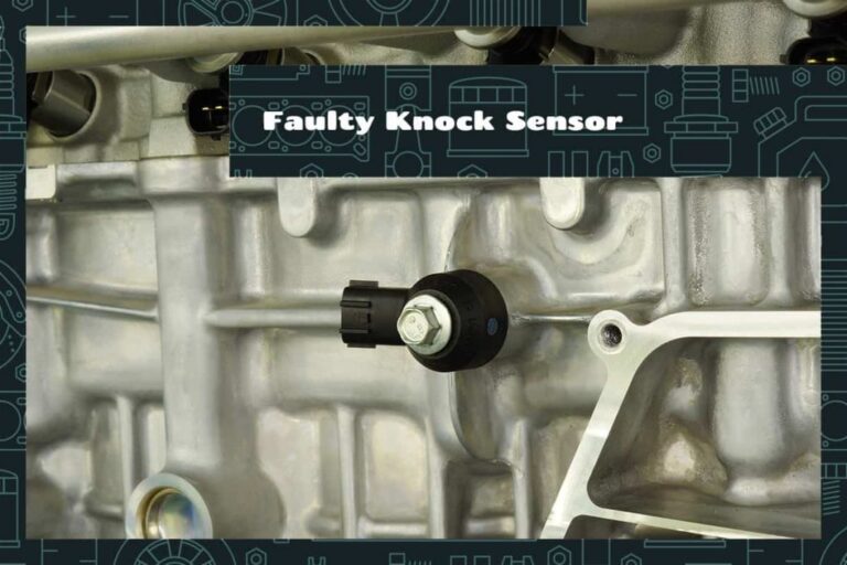
The knock sensor wire normally runs from the sensor through the engine harness to a dedicated ECU or PCM knock-signal circuit.
For vehicles sold in the United States, the exact knock sensor wiring depends on the year, engine, and engine control system. In most modern vehicles, the knock sensor sends a small electrical signal to the engine control module, commonly called the ECU or PCM. The module uses that signal to detect abnormal combustion and adjust ignition timing when needed.
A knock sensor wire does not usually connect directly to a generic power source. Depending on the vehicle, the sensor may use one signal wire, a signal and sensor-ground pair, or a shielded circuit. Some factory harnesses also use shielding or a drain connection to protect the low-level knock signal from electrical interference. The correct destination must therefore be confirmed with the wiring diagram for the specific vehicle.
Source: cimg2.ibsrv.net
Where Does the Knock Sensor Wire Go?
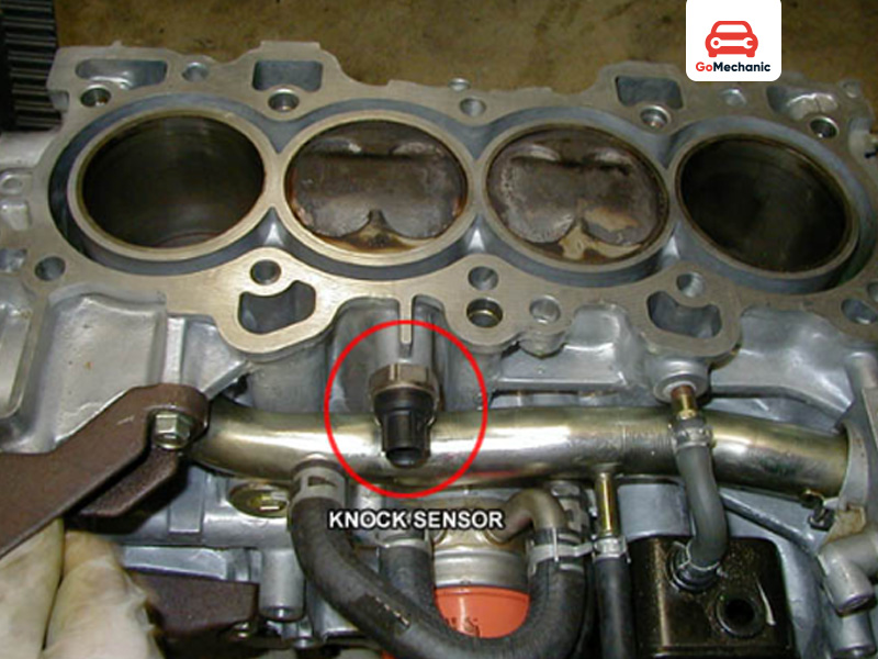
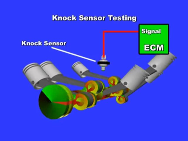
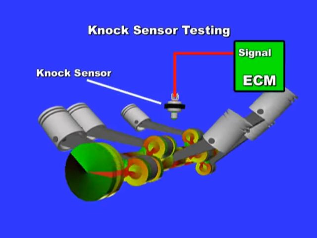
The knock sensor wire normally goes from the knock sensor on the engine to the ECU or PCM through the vehicle’s engine wiring harness. The sensor is usually mounted directly on the engine block or another location that lets it detect combustion-related vibration. From there, its electrical signal travels through a dedicated circuit to the engine computer.
The ECU or PCM monitors the signal rather than simply supplying ordinary power to the sensor. When the computer detects a signal associated with engine knock, its control strategy can respond by changing ignition timing and, depending on the vehicle, other engine parameters.
The exact route can vary substantially. A factory service manual may show the sensor connected directly to an ECM terminal, while another vehicle may route the circuit through one or more intermediate connectors. Some systems also include a separate sensor-ground or shield circuit.
Source: cimg9.ibsrv.net
Sensor end
The wire begins at the knock sensor connector or terminal located on or near the engine.
Engine harness
The circuit usually follows the factory engine harness toward an intermediate connector, bulkhead connection, or control-module harness.
ECU or PCM
The signal ultimately reaches a dedicated knock-sensor input at the engine control module.
Ground or shield
Depending on the design, a second circuit or shield may connect to sensor ground, engine ground, chassis ground, or a specified ECU circuit.
The Wire Does Not Have One Universal Destination
There is no universal knock sensor pin number, wire color, or connector location for every car sold in the United States. Even vehicles from the same manufacturer can use different circuits across engines and model years.
For example, factory service information for some vehicles identifies a dedicated ECM terminal for the knock signal and specifies a shielded section of harness. Other documented systems use separate knock-sensor inputs for multiple sensors. This is why matching the wiring to the exact vehicle is more reliable than following a generic pinout.
Do not rely on wire color alone
Wire colors can differ between models, engines, markets, and replacement harnesses.
Find the ECU terminal
The vehicle wiring diagram should identify the exact ECU or PCM connector and terminal receiving the knock signal.
How Knock Sensor Wiring Is Usually Arranged
Knock sensor circuits generally fall into a few common wiring arrangements. The most important distinction is whether the sensor uses one electrical connection, two dedicated connections, or additional shielding.
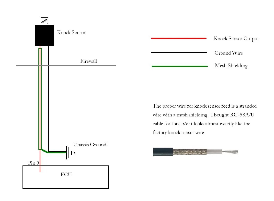
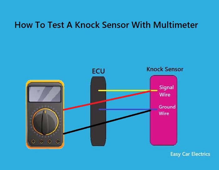
A one-wire knock sensor typically sends its signal through one conductor while the sensor body and engine provide the electrical return path. A two-wire design commonly has a dedicated signal connection and a separate return or sensor-ground connection. Some systems add a shield around the signal conductors to reduce interference.
The physical number of wires does not by itself tell you exactly where each wire should be connected. The factory diagram should identify the signal, ground, shield, and control-module terminals for that particular system.
Source: blogs.gomechanic.com
One-wire arrangement
One conductor carries the sensor signal, while the sensor body and engine can provide the return path on designs intended to work that way.
Two-wire arrangement
One wire normally carries the knock signal and the other provides the specified electrical return or sensor-ground connection.
Shielded arrangement
A shield surrounds part or all of the signal wiring to reduce electrical interference. The shield connection must follow the vehicle’s wiring design.
Why Knock Sensor Wiring May Be Shielded
The knock sensor produces a relatively small electrical signal, so the wiring can be susceptible to unwanted electrical interference. Factory harnesses may use shielded or twisted wiring to help preserve the signal as it travels to the ECU or PCM.
Service documentation for several vehicle systems specifically identifies the knock sensor harness as shielded. If the shielding is damaged, incorrectly grounded, or repaired in a way that changes the original circuit, the engine computer may receive an incorrect or unstable signal.
Do not treat the shield as an ordinary signal wire
The shield or drain conductor may have a specific grounding arrangement that differs from the sensor signal.
Preserve the factory routing
Keep the repaired circuit away from sources of unnecessary electrical interference and follow the original harness route where practical.
Where the Knock Sensor Wire Connects at the ECU or PCM
At the computer end, the knock sensor wire connects to a specific input terminal identified in the factory wiring diagram. The terminal may be labeled with an abbreviation such as KNK, KS, KNK1, or KNK2, although naming conventions vary by manufacturer.
Vehicles with two knock sensors can have separate inputs for each sensor. For example, a factory wiring diagram may identify one input as knock sensor 1 and another as knock sensor 2. Those circuits should not be swapped simply because the connectors look similar.
The computer-side connection can also include an intermediate harness connector. A factory diagnostic procedure may instruct a technician to check continuity from the knock sensor connector to the ECM terminal. This confirms that the complete circuit is intact rather than assuming that the visible portion of the wire is good.
Source: files.easybom.com
ECU or PCM terminal
This is the final electrical destination of the knock signal circuit.
Intermediate connector
Some vehicles route the circuit through one or more connectors between the engine sensor and control module.
Sensor ground
A separate ground circuit may terminate at a designated ECU sensor-ground terminal or another specified grounding point.
Shield or drain
A shield can terminate at a designated ground or shield connection depending on the manufacturer’s circuit design.
Why the ECU Pin Number Matters
A common wiring mistake is connecting the knock sensor wire to a nearby ECU terminal because the connector appears to fit. That can create an open circuit, a short circuit, or an incorrect sensor input. The correct terminal must be verified from the wiring diagram for the exact engine and model year.
Factory diagnostic procedures commonly check continuity between the ECU terminal and the knock sensor terminal. They may also check whether the circuit is shorted to ground or power. These checks are more reliable than guessing from connector position or wire color.
Verify the connector
Confirm the ECU or PCM connector identification before locating the terminal.
Verify the cavity
Use the wiring diagram to identify the exact terminal or cavity number.
Verify circuit continuity
With the required connectors disconnected, test the circuit according to the service manual.
How to Trace a Knock Sensor Wire
To find where the knock sensor wire goes on a specific vehicle, start with the factory wiring diagram rather than physically pulling the harness apart. The diagram can show the sensor connector, wire color, intermediate connectors, ECU or PCM terminal, grounds, and shielding.
Once the circuit is identified, trace it from the sensor toward the control module. Look for damaged insulation, stretched wires, corrosion inside connectors, loose terminals, previous repairs, and sections of harness that may have contacted hot or moving engine components.
If the engine computer has stored a knock-sensor-related diagnostic trouble code, use the manufacturer’s diagnostic sequence. A fault code can point toward the circuit, but it does not automatically prove that the sensor itself is defective.
Source: toolsweek.com
1. Identify the exact vehicle
Record the model year, engine, drivetrain where relevant, and engine control system before using a wiring diagram.
2. Locate the sensor connector
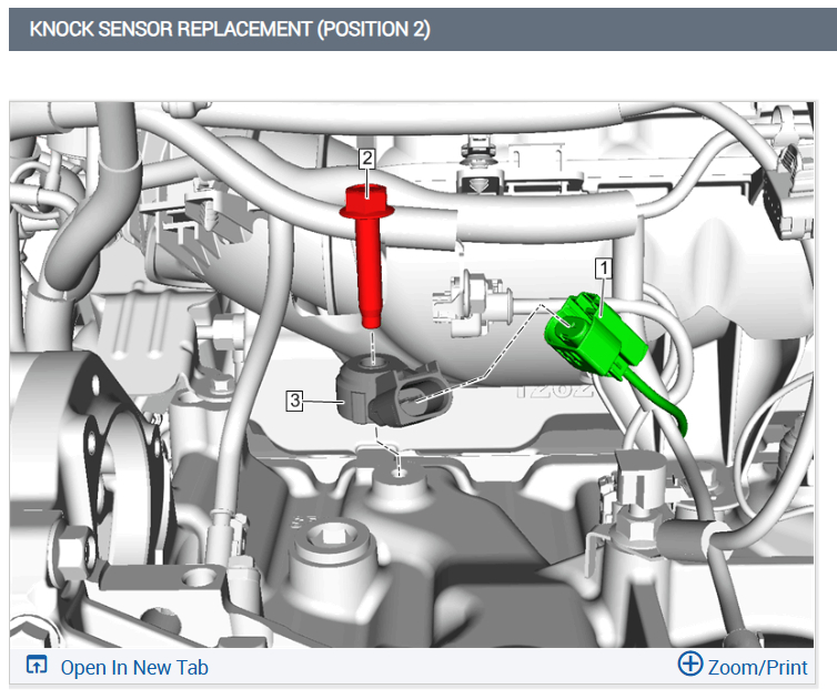
Find the knock sensor and identify its connector terminals using the service information.
3. Identify the ECU circuit
Follow the diagram from the sensor to the ECU or PCM and note every connector and terminal in between.
4. Inspect the harness
Check the accessible wiring for cuts, corrosion, chafing, melted insulation, loose terminals, and poor previous repairs.
5. Test continuity
With the appropriate connectors disconnected, check continuity between the specified sensor terminal and ECU terminal.
6. Check for unwanted shorts
Follow the service procedure to determine whether the circuit is accidentally shorted to ground, power, another circuit, or its shield.
Signs That the Knock Sensor Wire Has a Problem
A damaged knock sensor circuit can produce a check-engine light, a knock-sensor-related diagnostic trouble code, an implausible sensor reading, or a control system that cannot properly process the knock signal. The exact symptoms depend on the vehicle’s control strategy.
A circuit fault can sometimes resemble a bad knock sensor. That is why testing the wiring and connectors is useful before replacing the sensor. Factory diagnostic procedures for several vehicles specifically separate harness checks from sensor checks.
Open circuit
A broken conductor or disconnected terminal can prevent the ECU from receiving the sensor signal.
Short to ground
A damaged conductor can contact ground and change the expected electrical behavior of the circuit.
Short to power
Contact with an unintended powered circuit can produce an incorrect signal and may damage components.
Connector fault
Corrosion, loose terminals, or poor contact can interrupt the circuit without visible damage to the main wire.
How to Test the Knock Sensor Wire
Testing the knock sensor wire should follow the vehicle manufacturer’s procedure because resistance, voltage, connector access, and test conditions vary. In general, the first electrical checks involve continuity and unintended shorts rather than immediately replacing the sensor.
Disconnect the ignition power and the connectors required by the service procedure before performing resistance or continuity checks. Testing an energized circuit with an ohmmeter can produce incorrect results and may damage equipment or components.
A useful continuity check compares the appropriate knock sensor terminal with the specified ECU or PCM terminal. If the expected continuity is absent, inspect the wire and connectors for an open circuit. If the circuit shows an unexpected connection to ground or power, investigate the harness for insulation damage or an incorrect repair.
Source: i1.wp.com
Continuity check
Confirms that the intended conductor provides an electrical path between the sensor circuit and the ECU terminal.
Short-to-ground check
Determines whether the signal circuit is unintentionally connected to ground.
Short-to-power check
Determines whether the signal circuit is unintentionally connected to a powered circuit.
Connector inspection
Checks for corrosion, pushed-back terminals, damaged locks, poor contact, or contamination.
Do Not Guess the Expected Resistance or Voltage
There is no single resistance or voltage value that applies to every knock sensor. Factory procedures can specify different measurements depending on the sensor design and operating condition. Some systems also use a bias voltage from the engine computer, so a voltage reading can be misleading if it is interpreted without the service-manual specifications.
Use the exact test values and connector locations for the vehicle being repaired. If the service information requires a particular meter range, temperature, ignition state, or engine condition, follow those requirements.
Use the factory specification
Compare measurements with the exact vehicle and engine specification rather than a generic online value.
Observe test conditions
Record whether the test requires the ignition off, ignition on, engine running, or a specified engine temperature.
Common Knock Sensor Wiring Mistakes
The most common mistake is assuming that every knock sensor uses the same wiring arrangement. A generic diagram can explain the basic concept, but it cannot establish the correct ECU terminal, ground path, wire color, or shield connection for a particular vehicle.
Another mistake is replacing the sensor without checking the harness. A damaged wire between the sensor and ECU can create the same general diagnostic complaint as a failed sensor. Connector condition should also be considered because a loose or corroded terminal can interrupt a circuit even when the wire itself looks intact.
Source: cimg2.ibsrv.net
Using a generic pinout
A generic diagram may not match the exact engine or control module in the vehicle.
Connecting the shield incorrectly
Changing the factory shield or drain connection can affect signal integrity on systems that use shielded wiring.
Ignoring intermediate connectors
A fault may be located at a harness connector rather than at the sensor or ECU.
Testing without disconnecting connectors
Resistance and continuity tests should be performed under the conditions specified by the service information.
Using wire color as the only identification
Wire colors are useful clues but should be confirmed against connector and terminal information.
When a Wiring Repair Needs Extra Care
Take extra care when the knock sensor circuit uses shielded wiring. A repair that restores the signal conductor but leaves the shielding improperly connected may not reproduce the factory electrical arrangement.
Also use caution when working around the ECU or PCM. Avoid probing terminals in a way that spreads or damages connector contacts. A damaged control-module terminal can create a new intermittent fault that is harder to diagnose than the original wiring problem.
Protect connector terminals
Use appropriate back-probing or terminal-testing methods recommended for the connector.
Keep polarity and terminal identity correct
Follow the wiring diagram for sensors that have separate signal and ground connections.
What to Do If the Knock Sensor Wire Has Been Cut
If the knock sensor wire has been cut, identify every conductor before repairing it. Do not connect the wires solely by matching their apparent position or by assuming that all wires in the connector have the same function.
Use the wiring diagram to identify the signal conductor, sensor ground if present, and shield or drain. Then inspect both sides of the damaged section for corrosion, stretched copper, damaged insulation, or previous repairs. The replacement wire and repair method should be suitable for the engine-bay environment.
If the harness uses shielding, restore the shield according to the factory circuit. Do not automatically connect a shield to the nearest ground point because the manufacturer’s design may specify a particular grounding location.
Source: files.easybom.com
Identify before cutting
Confirm each conductor and its ECU or PCM destination before making a repair.
Remove damaged sections
Do not leave severely corroded or heat-damaged conductor material inside a repair.
Restore the original circuit
Preserve the signal, ground, shielding, connector arrangement, and harness routing specified for the vehicle.
Retest after repair
Repeat the required continuity and short checks before reconnecting components and clearing diagnostic faults.
When to Use a Professional Repair
A professional diagnostic technician is a sensible choice when the wiring diagram is unavailable, the ECU connector has been damaged, several harness wires are affected, or the circuit uses complex shielding and multiple connectors. The same applies when repeated wiring repairs have not resolved the diagnostic fault.
If the engine has a severe drivability problem, persistent warning light, or evidence of harness damage near hot exhaust components, avoid guessing at the wiring. Incorrect electrical connections can create additional faults and, in some cases, damage electronic control components.
Complex harness damage
Multiple damaged circuits can make color-based tracing unreliable.
Damaged ECU connector
Terminal repair may require specialized tools and connector information.
Unresolved diagnostic fault
If wiring tests pass but the fault remains, follow the complete manufacturer diagnostic procedure rather than replacing parts at random.
Frequently Asked Questions
Q
Does the knock sensor wire go directly to the ECU?
The knock sensor circuit ultimately connects to a dedicated ECU or PCM input, but it may pass through intermediate connectors in the engine and body harness. The exact route depends on the vehicle.
Use the factory wiring diagram to identify the complete path and the correct control-module terminal.
Q
Where does a one-wire knock sensor ground?
Many one-wire knock sensor designs use the sensor body and engine block as the electrical return path. However, this is not a universal rule for every sensor or vehicle.
Confirm the grounding method in the vehicle’s wiring diagram before adding a separate ground wire.
Q
Where does the second knock sensor wire go?
On a two-wire design, the second conductor commonly serves as the sensor return or ground circuit. It may connect to a specified sensor-ground circuit at the ECU or to another manufacturer-defined grounding point.
Do not assume that the second wire is chassis ground without checking the wiring diagram.
Q
Does a knock sensor wire need to be shielded?
Some factory knock sensor circuits use shielded wiring, while others do not. Shielding is used on certain systems to reduce electrical interference around the low-level knock signal.
If the original harness is shielded, preserve the specified shield and drain arrangement during repairs.
Q
Can a broken knock sensor wire cause a check-engine light?
Yes. An open circuit, short circuit, poor connector connection, or damaged shield can prevent the ECU from receiving the expected knock sensor signal and may trigger a diagnostic trouble code.
The exact code and symptoms vary by vehicle, so the wiring should be tested before assuming the sensor itself has failed.
Q
Can I connect a knock sensor wire to any engine ground?
No. A knock sensor circuit should be connected according to the manufacturer’s wiring design. Some systems use the engine block as the return path, while others use a dedicated sensor-ground circuit.
An incorrect ground connection can change the sensor signal and create diagnostic problems.
✦ Wrapping Up
Conclusion
The knock sensor wire normally runs from the sensor through the engine harness to a dedicated input at the ECU or PCM. Depending on the vehicle, the circuit can include a signal wire, sensor ground, shield, intermediate connectors, or separate inputs for multiple knock sensors.
Because knock sensor wiring is vehicle-specific, the safest way to determine exactly where the wire goes is to use the factory wiring diagram for the exact model year and engine. Trace the circuit from the sensor to the ECU, inspect connectors and wiring, and perform continuity and short checks using the manufacturer’s test procedure.
💡 Key Takeaway
Before repairing or reconnecting a knock sensor wire, identify the exact ECU terminal, sensor terminal, ground path, and shield arrangement in the vehicle-specific wiring diagram, then verify the circuit with the correct electrical tests.
Ethan Brooks is an automotive writer at Auto News 7, covering car news, vehicle maintenance, new model updates, recalls, and practical buying guides. He focuses on clear, useful information that helps drivers understand their vehicles and make better ownership decisions.
Learn whether a knock sensor affects acceleration, how a faulty knock sensor impacts engine performance, common symptoms, diagnostic steps, and when replacement is necessary.
Learn when to replace a crankshaft position sensor, how to recognize failure symptoms, diagnose the problem, and avoid replacing a good sensor unnecessarily.
Learn whether camshaft sensors are interchangeable, how to identify compatible sensors, common mistakes to avoid, and how to choose the correct replacement for your vehicle.