Test a 2 wire knock sensor by checking its specified resistance, wiring continuity, shorts, and signal behavior.
If you are diagnosing a check-engine light on a U.S.-market vehicle, a 2 wire knock sensor can often be checked with a digital multimeter before replacing parts. The basic procedure is simple, but the correct resistance value depends on the vehicle, engine, sensor design, and service information.
A 2 wire knock sensor normally uses two electrical connections for the sensor circuit. Many knock sensors use a piezoelectric element that responds to engine vibration and produces an electrical signal for the engine control module. Because designs differ, a resistance reading that looks reasonable on one vehicle may be incorrect on another.
The safest approach is to identify the exact vehicle specification first, disconnect the sensor, and compare the measured value with the manufacturer’s service specification. Then test the harness separately so a wiring problem is not mistaken for a failed sensor.
Source: youtube.com
What Is a 2 Wire Knock Sensor?
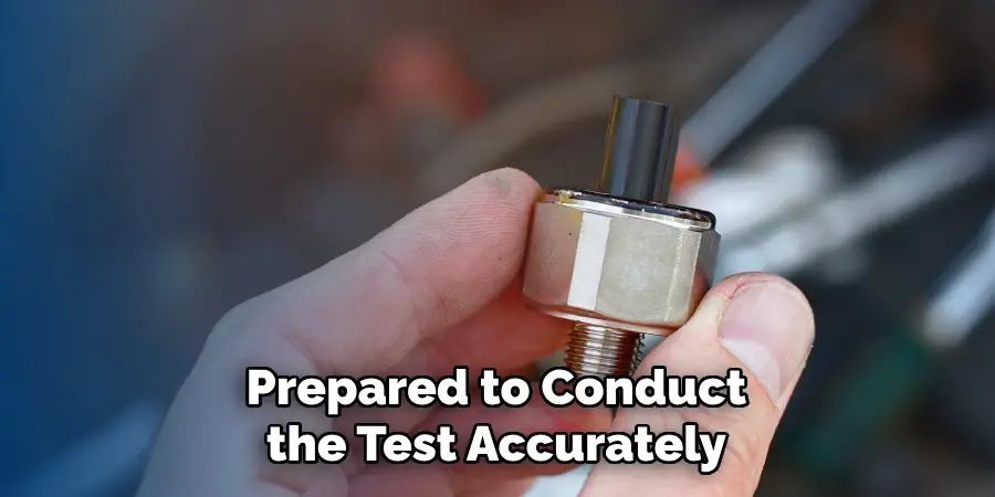
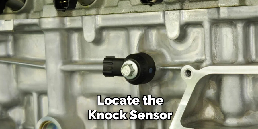
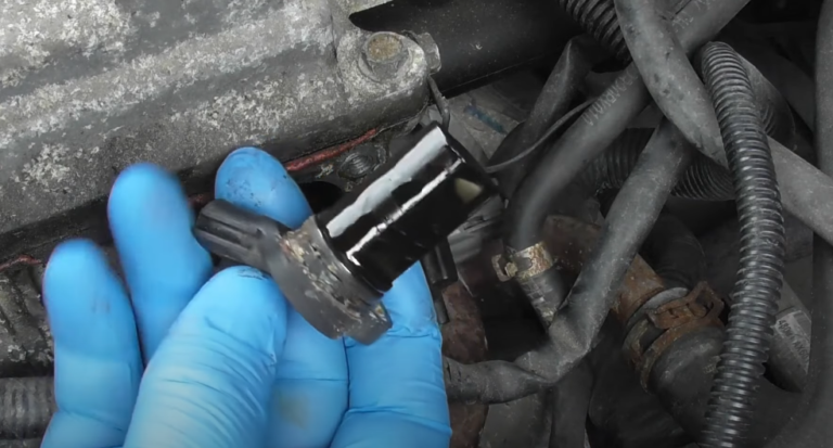
A 2 wire knock sensor is an engine sensor that detects vibration associated with combustion knock or detonation. The sensor is commonly mounted to the engine block, where it can detect vibration and send an electrical signal to the engine control module.
The two wires form the electrical circuit between the sensor and the vehicle’s control system. Depending on the vehicle, one wire may carry the sensor signal while the other provides a return or reference path. Some systems also use shielding or specific grounding arrangements, so the wiring diagram matters.
The key point is that 2 wire does not mean one universal electrical design. Service manuals show different resistance specifications and circuit arrangements across vehicles.
Source: easycarelectrics.com
Sensor
The knock sensor detects vibration and converts mechanical vibration into an electrical signal.
Two-wire circuit
The two electrical terminals connect the sensor to the engine control system through the vehicle harness.
Engine control module
The control module interprets the sensor signal as part of its engine-control strategy.
What You Need Before Testing a 2 Wire Knock Sensor
You need a digital multimeter and access to the vehicle’s service information. The service information is especially important because the correct resistance value, terminal identification, and circuit-testing procedure vary by vehicle.
Park the vehicle securely and switch the ignition off before disconnecting the sensor. Let hot components cool when necessary. Keep hands, clothing, and test leads away from belts, pulleys, fans, and other moving parts whenever an engine-running test is required.
A scan tool can also help if the vehicle has a knock-sensor diagnostic trouble code. Codes such as P0327 and P0328 can point toward a low or high input condition, but a trouble code does not by itself prove that the sensor is defective.
Source: electrozlab.com
Digital multimeter
Use a meter that can accurately measure the resistance range specified by the vehicle manufacturer.
Vehicle service information
Find the correct sensor resistance, terminal numbers, wiring diagram, and diagnostic procedure for the exact vehicle.
Basic inspection tools
A flashlight and suitable hand tools can help you access the connector and inspect the wiring.
Optional scan tool
A scan tool can read diagnostic trouble codes and, on some vehicles, monitor knock-sensor-related data.
How to Test a 2 Wire Knock Sensor With a Multimeter
The basic test is to measure resistance across the two sensor terminals with the sensor disconnected. However, the measured value must be compared with the exact specification for your vehicle. There is no universal resistance number for every 2 wire knock sensor.
For example, published service information for some Nissan applications specifies approximately 532 to 588 kΩ at 20°C (68°F), while other vehicles use very different specifications. A Mazda service procedure, for example, lists approximately 4.87 MΩ for one application. These differences show why a generic resistance rule can lead to a wrong diagnosis.
Source: youtube.com
Step 1: Identify the sensor
Locate the knock sensor and verify that it has two electrical terminals. Use the wiring diagram to identify the correct connector and terminals.
Step 2: Turn the ignition off
Switch the ignition off before disconnecting the knock sensor. Follow any additional waiting period or battery-disconnection instruction specified by the service manual.
Step 3: Disconnect the connector
Release the connector carefully without pulling on the wires. Inspect the terminals for corrosion, looseness, contamination, or physical damage.
Step 4: Set the multimeter
Select resistance mode and choose a range that can accurately measure the manufacturer’s specified value. An autoranging meter is suitable when it provides sufficient resolution.
Step 5: Measure the sensor
Place one meter probe on each of the two sensor terminals. Do not use the harness terminals for this sensor-resistance test.
Step 6: Record the reading
Write down the resistance and the approximate sensor temperature if the service specification is temperature-dependent.
Step 7: Compare with the specification
Compare the measurement with the exact factory specification. A reading outside the specified range can indicate a faulty sensor, but the complete diagnostic procedure should be followed before replacement.
What Resistance Reading Should a 2 Wire Knock Sensor Have?
There is no single resistance value that applies to every 2 wire knock sensor. Published service procedures show substantial differences between applications. One Nissan service procedure specifies approximately 532 to 588 kΩ at 20°C (68°F), while a Mazda procedure for a different application specifies approximately 4.87 MΩ.
Some other service procedures specify still different values. Therefore, do not condemn a sensor simply because its resistance does not match a number found for another vehicle online.
Temperature can also affect resistance on some sensors. When the service information gives a temperature condition, perform the test under the specified condition or account for the stated temperature range.
Within specification
The resistance matches the manufacturer’s stated range under the required test conditions. Continue with wiring and signal checks if a fault remains.
Very high or open
An open circuit or resistance far above the specified range can indicate an internal sensor or connection problem.
Very low
A reading far below specification can indicate an internal short or another sensor problem.
How to Test the 2 Wire Knock Sensor Wiring
If the sensor resistance is correct but the vehicle still reports a knock-sensor fault, test the wiring. A sensor cannot communicate correctly with the engine control module if either circuit is open, shorted, damaged, or poorly connected.
Disconnect the sensor and follow the vehicle’s wiring diagram. Many factory procedures require checking continuity between each sensor circuit and the corresponding engine control module terminal. They may also require checking for unintended continuity to ground or power.
Use the resistance limits specified by the vehicle manufacturer. Some service procedures use very low resistance limits for a good wire, while others specify different values depending on circuit length and design.
Source: storage.googleapis.com
Check continuity
Verify that each sensor circuit has continuity between the appropriate sensor connector terminal and the corresponding control-module circuit.
Check for shorts
Check the sensor circuits for unintended continuity to ground, power, or another circuit when the service procedure calls for those checks.
Inspect connectors
Look for corrosion, pushed-back terminals, damaged locks, loose connections, or contamination.
Inspect the harness
Look for chafed, pinched, stretched, melted, or broken wires, especially near the engine and sensor mounting area.
Why Sensor Testing and Wiring Testing Must Be Separate
A resistance test performed directly across the sensor evaluates the sensor itself. A continuity test performed on the harness evaluates the wiring. Mixing these two tests can produce misleading results.
For example, a sensor may have the correct resistance while one harness wire has an internal break. Conversely, a good harness can connect to a sensor whose internal element is outside specification.
Sensor test
Measure the sensor terminals directly with the connector disconnected.
Harness test
Test the vehicle wiring separately using the wiring diagram and specified terminals.
How to Diagnose a Knock Sensor That Tests Good
If the resistance is within specification and the wiring passes continuity and short checks, do not automatically replace the sensor. The remaining fault may involve the connector, sensor mounting, signal circuit, engine control module, or an intermittent wiring problem.
A knock sensor must be mounted correctly to detect engine vibration. Follow the manufacturer’s installation procedure for mounting location, fastener type, tightening method, and torque. Do not assume that tightening the sensor as hard as possible is correct.
Some diagnostic procedures also monitor sensor data while engine speed changes. Such tests should follow the vehicle’s service instructions because the acceptable signal behavior varies by system.
Source: storage.googleapis.com
Check the connector again
A terminal can look clean but still have poor contact tension or an intermittent connection.
Check sensor mounting
Verify that the sensor is installed at the specified location and secured according to the manufacturer’s procedure.
Check for intermittent faults
Inspect the harness for damage that may appear only when the engine moves or reaches operating temperature.
Use scan data when available
Follow the manufacturer’s diagnostic procedure for evaluating live knock-sensor or related engine-control data.
Common Mistakes When Testing a 2 Wire Knock Sensor
The most common mistake is using a resistance specification from a different vehicle. Knock sensors that look similar can have substantially different electrical characteristics, so always use the specification for the exact application.
Another mistake is testing the sensor with the connector still attached to the vehicle harness. Unless the service procedure specifically calls for that test, disconnect the sensor before measuring its resistance.
Avoid applying battery voltage directly to the sensor as a generic test. A knock sensor is not a simple powered switch, and an incorrect voltage test can damage components or produce meaningless results.
Source: safetywish.com
Using a generic resistance value
Different sensors can have very different resistance specifications. Use the exact vehicle specification.
Testing the wrong terminals
Confirm terminal identification with the wiring diagram before connecting the meter.
Ignoring temperature
Some resistance specifications are given at a particular temperature. Record the test conditions when temperature affects the specification.
Replacing the sensor immediately
Check the wiring, connector, mounting, and diagnostic code conditions before concluding that the sensor itself has failed.
Working around a running engine carelessly
Keep hands, tools, clothing, and meter leads away from moving or hot engine components during any running-engine diagnostic procedure.
What the Test Results Mean
The result should be interpreted as part of a diagnostic sequence rather than as a single pass-or-fail number. A resistance reading outside the manufacturer’s specification provides useful evidence of a sensor problem, but a correct resistance reading does not guarantee correct signal behavior.
Use the following decision process to determine the next check. Start with the sensor, then move to the wiring and connector, and finally follow the vehicle-specific diagnostic procedure for signal and control-module checks.
Source: youtube.com
Resistance is outside specification
Follow the service manual’s next diagnostic step. The sensor may be defective, but confirm the test conditions and terminal identification first.
Resistance is correct but a fault remains
Test the wiring, connector, mounting, and signal circuit according to the vehicle-specific procedure.
Wiring has an open circuit
Repair the affected circuit using the manufacturer’s wiring repair requirements, then clear and retest the fault as directed.
Wiring is shorted
Locate the unintended connection to ground, power, or another circuit before replacing the sensor.
Everything passes
Continue with the manufacturer’s diagnostic procedure for intermittent faults, signal evaluation, related engine conditions, and control-module diagnosis.
When to Stop Testing and Get Professional Help
Stop and seek qualified automotive help if the sensor is difficult to access, the test requires working near moving engine components, or the wiring diagram and specifications are unavailable. Modern engine-control systems can use low-level sensor signals that are easy to misdiagnose without the correct service information.
Professional diagnosis is also appropriate when the sensor passes a resistance test but the vehicle continues to set a knock-sensor fault. At that point, the problem may require oscilloscope testing, manufacturer-specific scan data, advanced wiring tests, or additional engine diagnostics.
Source: safetyfic.com
Use manufacturer specifications
Do not proceed with a component replacement based only on a generic online resistance value.
Avoid unsafe live testing
Do not place hands or tools near belts, pulleys, fans, exhaust components, or other hazards while the engine is running.
Protect electronic components
Use the specified test points and adapters when the service procedure warns against probing control-module connectors directly.
Frequently Asked Questions
Q
Can I test a 2 wire knock sensor with a multimeter?
Yes. A digital multimeter can be used to measure resistance across the two sensor terminals when the sensor is disconnected. The reading must be compared with the exact specification for the vehicle.
A multimeter resistance test is only one part of a complete diagnosis. Wiring, connectors, mounting, and signal behavior may also need to be checked.
Q
What resistance should a 2 wire knock sensor have?
There is no universal resistance value for every 2 wire knock sensor. Different vehicle manufacturers and engine applications use different sensor designs and specifications.
Always use the service specification for the exact vehicle, including any required temperature condition.
Q
Should a knock sensor have continuity?
The answer depends on what is being tested. The sensor itself should be evaluated using its specified resistance between its terminals, while the vehicle harness should be checked separately for continuity between the specified circuit points.
Do not assume that a generic continuity beep proves that the complete knock-sensor system is functioning correctly.
Q
Can a bad knock sensor cause a check engine light?
Yes. A malfunctioning knock sensor or its circuit can cause the engine control module to store a diagnostic trouble code and illuminate the check-engine light.
However, the same type of fault can also result from wiring problems, connector problems, or other conditions. The diagnostic code should be followed by the manufacturer’s testing procedure.
Q
What if the knock sensor resistance is good but the code remains?
Continue with the wiring and signal checks in the vehicle service procedure. A normal resistance reading does not prove that the sensor produces the correct signal in every operating condition.
Inspect the connector and harness, verify sensor mounting, and check for intermittent faults before replacing parts.
Q
Can I test a knock sensor while the engine is running?
Some manufacturer procedures include engine-running tests, but the exact procedure varies by vehicle. A basic resistance test should normally be performed with the sensor disconnected and the ignition off.
Only perform a running-engine test when the service information specifically calls for it and you can safely avoid moving, hot, and rotating components.
✦ Wrapping Up
Conclusion
Testing a 2 wire knock sensor starts with a simple resistance measurement, but accurate diagnosis requires more than a single multimeter reading. Disconnect the sensor, measure its two terminals, and compare the result with the exact specification for the vehicle and test conditions.
If the sensor passes, move to the harness, connector, mounting, and signal checks. Because knock-sensor designs vary widely, avoid generic resistance numbers and do not replace a sensor until the vehicle-specific diagnostic procedure supports that conclusion.
💡 Key Takeaway
Use the exact vehicle service specification, test the disconnected sensor first, then check the wiring and signal circuit before replacing the knock sensor.
Ethan Brooks is an automotive writer at Auto News 7, covering car news, vehicle maintenance, new model updates, recalls, and practical buying guides. He focuses on clear, useful information that helps drivers understand their vehicles and make better ownership decisions.
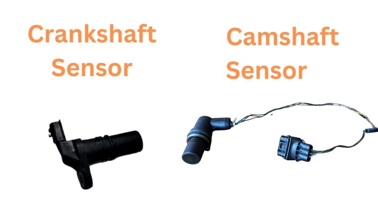
Learn whether camshaft and crankshaft sensors are the same, how they work, their differences, symptoms of failure, and when each sensor needs replacement.
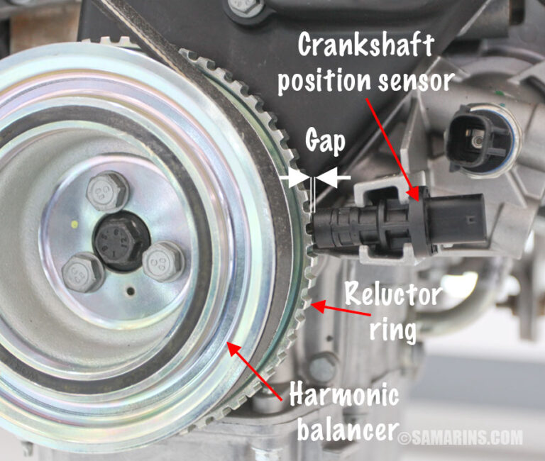
Can a bad crankshaft sensor cause misfire? Learn how a faulty crankshaft position sensor can disrupt engine timing, trigger misfires, and cause stalling.
Learn whether camshaft sensors are interchangeable, how to identify compatible sensors, common mistakes to avoid, and how to choose the correct replacement for your vehicle.
Learn what a camshaft position sensor looks like, where it is located, how to identify it, and how it differs from other engine sensors. Includes photos, features, and troubleshooting tips.
Learn how much to replace a camshaft position sensor in the United States, including parts, labor, DIY costs, symptoms, and factors that affect repair pricing.