To replace a crankshaft sensor wiring harness, identify the damaged circuit, disconnect power, repair or replace the wiring, and verify the sensor signal.
For drivers and DIY mechanics in the United States, a damaged crankshaft sensor wiring harness can cause hard starting, stalling, a no-start condition, or a check engine light. The crankshaft position sensor sends engine-speed and position information to the engine control module, so a reliable electrical connection is essential for proper engine operation.
The repair is not always a complete harness replacement. A damaged connector, broken conductor, corroded terminal, or chafed section may be repairable with the correct vehicle-specific harness repair procedure. Before cutting any wire, use the wiring diagram and service information for the exact year, make, model, engine, and sensor type. Crankshaft circuits vary substantially between vehicles.
This guide explains how to replace a crankshaft sensor wiring harness safely, how to confirm that the wiring is actually the problem, and how to check the repair afterward. The procedures below are general guidance rather than a substitute for the manufacturer’s wiring diagram, connector pinout, wire specifications, torque specifications, or repair instructions.
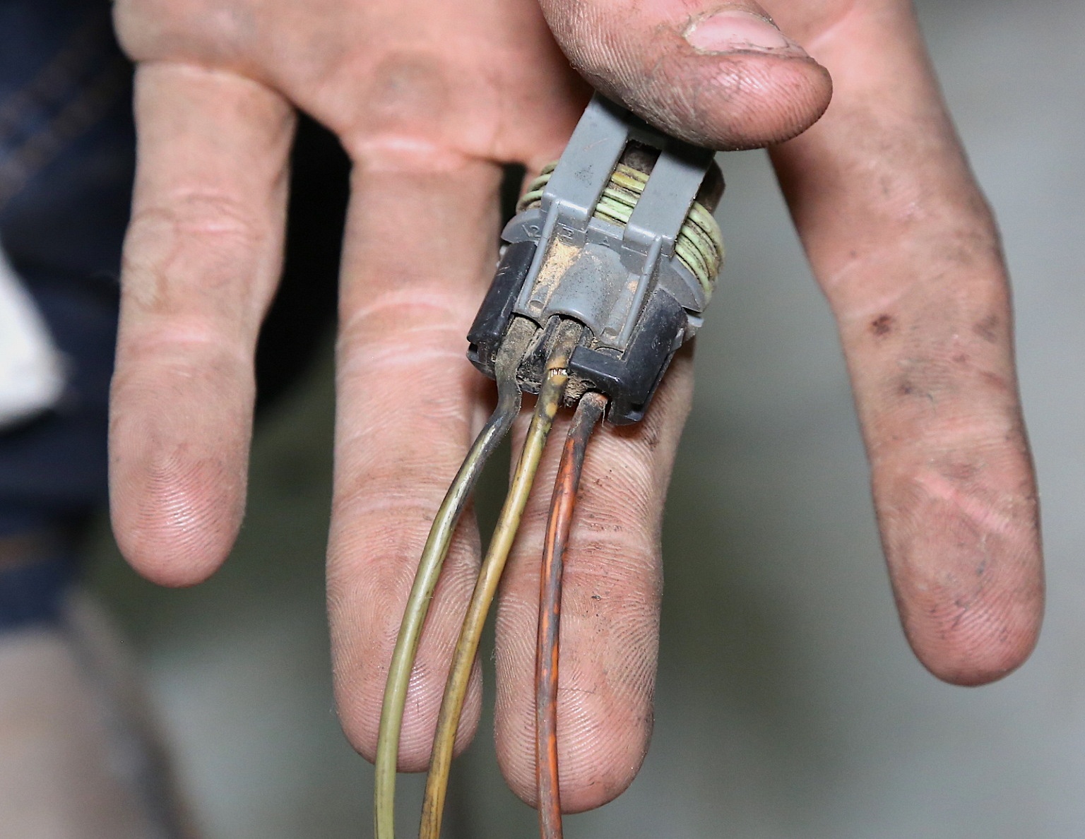
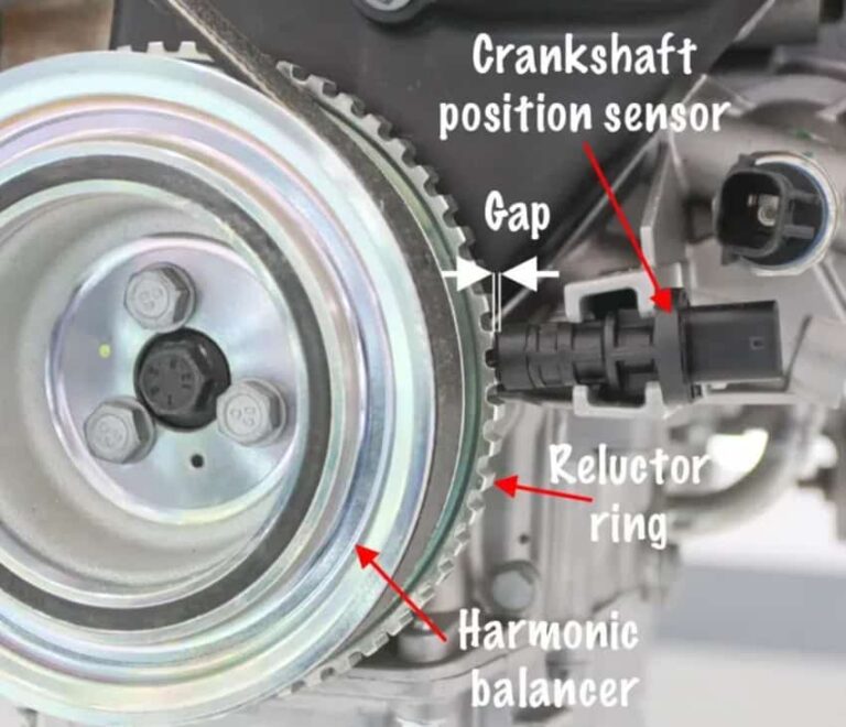
Source: nissankaengine.com
What Is a Crankshaft Sensor Wiring Harness?
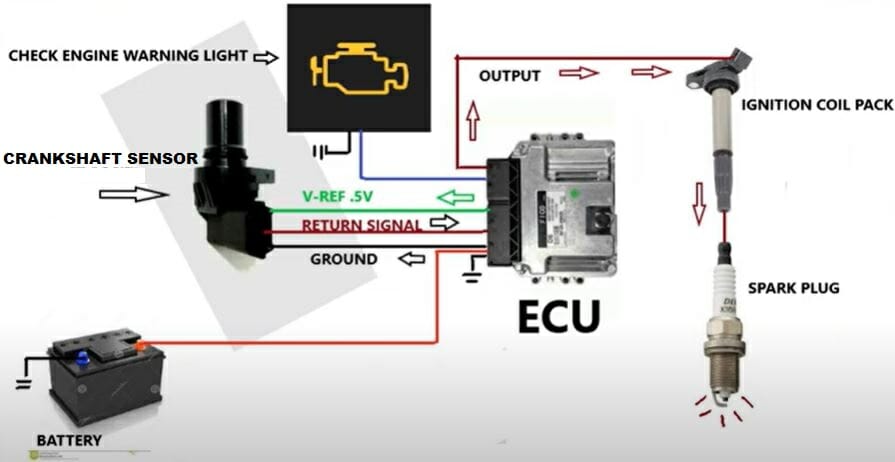
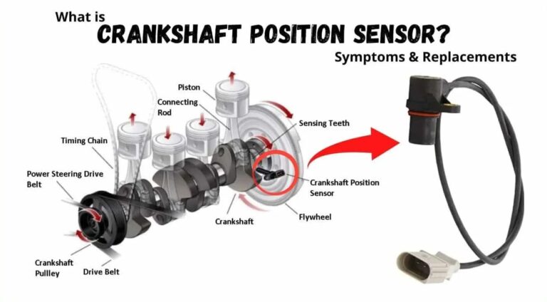
The crankshaft sensor wiring harness is the group of wires and connectors that links the crankshaft position sensor to the vehicle’s engine control module and, depending on the design, its power and ground circuits. The crankshaft position sensor, often called the CKP sensor, detects crankshaft position and rotational speed.
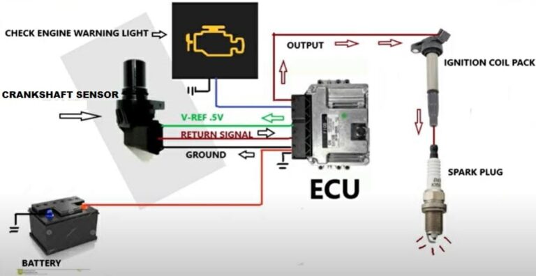
The engine computer uses the CKP signal for functions such as ignition timing, fuel injection control, engine-speed calculation, and synchronization. If the electrical path is open, shorted, badly corroded, or intermittently connected, the engine computer may receive an incorrect or missing signal.
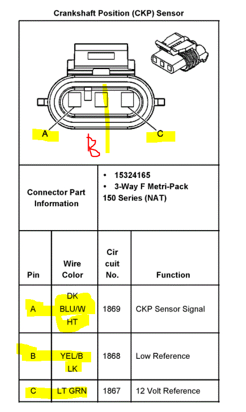
Some crankshaft sensors use two wires, while other designs use three or more. Hall-effect sensors commonly require power, ground, and a signal circuit. Variable-reluctance sensors can use a different electrical arrangement. Never assume that wire color or pin position from another vehicle applies to yours.
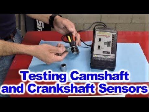
Source: youtube.com
Sensor connector
The connector joins the crankshaft sensor to the vehicle harness and can develop corrosion, loose terminals, broken locking tabs, or poor terminal contact.
Harness wires
The wires carry the sensor’s electrical signal and, depending on the design, power, ground, or shielding between the sensor and control module.
Engine control module
The engine control module receives and interprets the crankshaft signal. A good sensor cannot produce a usable result if the signal cannot reach the module.
When Should You Replace the Crankshaft Sensor Wiring Harness?
Replace or repair the crankshaft sensor wiring when testing confirms an electrical fault and the damage cannot be corrected by securing or cleaning the existing connection. A complete harness replacement is not automatically necessary for every wiring problem.
Common evidence includes a broken conductor, melted insulation, severe chafing, damaged terminals, corrosion that has migrated into the connector or wire, or an intermittent signal that changes when the harness is moved. A wiring fault may also remain after a new crankshaft sensor has been installed.
A diagnostic trouble code such as P0335 can point toward a crankshaft position sensor circuit problem, but the code does not by itself prove that the sensor or its harness is defective. Scan data, visual inspection, electrical testing, and the vehicle’s wiring information should be used together.
Source: vehiclechef.com
Visible wire damage
Look for exposed copper, crushed sections, melted insulation, severe abrasion, rodent damage, or wires pulled tight against engine components.
Connector damage
Inspect for bent, recessed, loose, corroded, contaminated, or broken terminals and damaged connector locks.
Intermittent fault
A vehicle that loses the crankshaft signal when the harness is gently moved may have an internal conductor break or poor connection.
Repeated sensor failure
If replacement sensors continue to produce the same fault, investigate the wiring, connector, power supply, ground, sensor target, and control module circuit before installing another sensor.
Tools and Parts You May Need
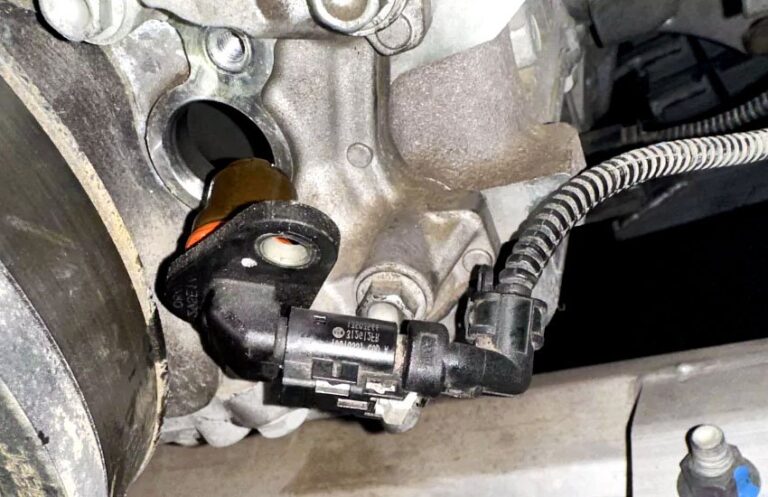
The required tools depend on the vehicle and the location of the crankshaft sensor. Before starting, obtain the manufacturer’s wiring diagram and repair procedure. You may need to access the sensor from above, below, or through a wheel well, so follow the vehicle manufacturer’s lifting instructions.
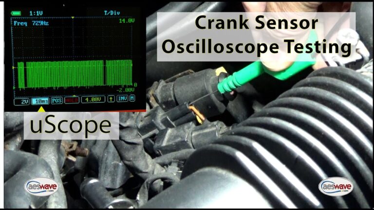
For electrical diagnosis, a quality digital multimeter is useful for checking continuity, resistance, and voltage when the manufacturer’s specifications call for those measurements. An oscilloscope can provide more detailed information about the actual crankshaft sensor waveform and can help identify intermittent signal problems that a simple continuity test may miss.
Use wire, terminals, seals, connector components, and splicing materials that meet the vehicle manufacturer’s specifications. Do not substitute household wire, twist-and-tape connections, or unsuitable crimp connectors in an engine compartment.
Source: toolsweek.com
Basic tools
Prepare sockets, ratchets, screwdrivers, trim tools, cutters, wire strippers, crimping tools, and suitable lighting as required by the vehicle.
Electrical test equipment
A digital multimeter is commonly used for basic circuit testing. A suitable oscilloscope can provide additional information about the sensor waveform.
Repair materials
Use vehicle-appropriate wire, terminals, seals, connector components, and approved splice materials.
Safety equipment
Use eye protection and suitable gloves, and support a raised vehicle with properly rated equipment rather than relying on a jack alone.
How to Diagnose the Crankshaft Sensor Wiring Before Replacing It
Start with diagnosis rather than cutting the harness. A no-start condition or crankshaft-related trouble code can have several causes, including a failed sensor, damaged wiring, poor connector contact, an incorrect sensor installation, a damaged tone or reluctor wheel, or a control-system problem.
Read the stored diagnostic trouble codes and record relevant freeze-frame information before clearing anything. Then inspect the sensor and harness. Look for rubbing against brackets, exhaust heat damage, oil contamination, water intrusion, previous repairs, stretched wires, and connector damage.
Next, identify the exact circuit from the wiring diagram. Determine which terminal is the sensor signal, which is ground or return, and which is power if the sensor requires a supply. Some crankshaft circuits are sensitive to electrical interference, so shielding and routing can matter as much as basic continuity.
Test the circuit according to the manufacturer’s specifications. A continuity check can find an open circuit, but continuity alone does not prove that a circuit will perform correctly under operating conditions. Where appropriate, compare the sensor signal at the sensor with the signal reaching the engine control module.
A useful diagnostic approach is to monitor the signal while gently moving the harness without pulling or stressing it. If the signal disappears when a damaged area is moved, that provides strong evidence of an intermittent harness fault. Professional diagnostic procedures may use breakout equipment and an oscilloscope to compare the sensor output with the signal arriving at the control module.
Source: 2carpros.com
Check the code
A crankshaft-related trouble code identifies a circuit or performance concern but does not automatically identify the failed component.
Inspect the complete harness
Follow the harness from the crankshaft sensor toward the engine control module and inspect areas exposed to heat, vibration, fluids, sharp edges, and previous repairs.
Verify the connector
Check terminal condition, connector locking, corrosion, moisture, and whether terminals are securely retained.
Test the circuit
Use the vehicle-specific pinout and electrical specifications to check continuity, resistance, power, ground, and signal as applicable.
Check the signal
When required, use a scan tool or oscilloscope to confirm that a usable crankshaft signal is being generated and reaching the control module.
Why a Continuity Test Is Not Always Enough
A wire can show continuity with a multimeter and still have an intermittent fault. A conductor may be fractured inside its insulation, or a terminal may lose contact when vibration or engine movement changes the connection. For difficult faults, testing the signal while the harness is monitored can reveal problems that a static continuity test misses.
Do not pierce insulation unnecessarily when testing. Use suitable back-probing or breakout equipment where possible, because damaged insulation can create another failure point.
Static continuity
Useful for finding an open circuit, but it does not reproduce every operating condition.
Loaded circuit testing
Can reveal voltage-drop or connection problems that are not obvious during a simple resistance check.
Waveform testing
An oscilloscope can show whether the crankshaft sensor produces the expected signal and whether that signal remains intact through the harness.
How to Replace a Crankshaft Sensor Wiring Harness
Once testing confirms that the harness is damaged, determine whether the manufacturer provides a connector repair, pigtail replacement, individual wire repair, or complete harness replacement procedure. The correct approach depends on the vehicle and the location and extent of the damage.
Disconnect the vehicle’s electrical power as required by the manufacturer’s procedure before working on the circuit. If the vehicle must be raised, use the specified lifting points and support it securely. Keep the ignition off and prevent accidental engine cranking while wiring is being repaired.
Source: safetyfic.com
Step 1: Document the original routing
Photograph and note how the harness is routed, clipped, retained, and separated from hot or moving components before removing it.
Step 2: Disconnect the sensor
Release the crankshaft sensor connector carefully. Do not pull on the wires to separate the connector.
Step 3: Disconnect the harness as required
Follow the wiring toward its other connection points and disconnect only the components required by the vehicle-specific repair procedure.
Step 4: Remove damaged wiring
If repairing a section rather than replacing the complete harness, remove only the damaged portion and preserve enough original wire for a secure, properly supported repair.
Step 5: Match the replacement wire
Use the correct wire type, conductor size, insulation characteristics, terminal style, and shielding requirements specified for the circuit.
Step 6: Make the electrical repair
Use the manufacturer’s approved terminal or splice method. Keep connections mechanically secure and properly insulated from moisture and abrasion.
Step 7: Repair the connector if necessary
If the connector or terminals are damaged, install the specified replacement connector or terminals rather than forcing damaged terminals back into service.
Step 8: Route the harness correctly
Restore the original routing and retainers. Keep the harness away from exhaust components, belts, pulleys, sharp edges, and locations where engine movement can pull on the wires.
Step 9: Reconnect the sensor
Make sure the connector is fully seated and locked. Verify that the wires are not under tension at the connector.
Step 10: Reconnect vehicle power
Restore electrical power according to the manufacturer’s procedure and inspect the completed repair before attempting to start the engine.
Step 11: Test the circuit
Repeat the applicable continuity, resistance, voltage, and signal checks to confirm that the repaired circuit meets the vehicle’s specifications.
Step 12: Test the engine
Start the vehicle when appropriate, monitor engine-speed and crankshaft-related data, and check for returning diagnostic trouble codes.
How to Make a Reliable Wire Splice
A harness repair should be mechanically secure and electrically sound. The exact splice method should follow the vehicle manufacturer or approved repair-system instructions. Do not simply twist wires together and cover the joint with electrical tape.
Before making the splice, confirm that the replacement wire matches the original circuit requirements. Strip only the amount required by the approved connector or splice method. After completing the connection, protect it against moisture, heat, vibration, and abrasion according to the repair instructions.
Keep the repaired section positioned so it is not pulled tight when the engine moves. A splice placed directly against a connector or a high-vibration mounting point may be more vulnerable to mechanical stress.
Use the correct wire
Match the original circuit’s conductor and insulation requirements rather than choosing wire based only on appearance.
Maintain circuit integrity
Preserve any required shielding, twisted-pair arrangement, polarity, and circuit separation specified by the manufacturer.
Protect the repair
Seal and support the repaired section so moisture, abrasion, heat, and vibration do not create another failure.
When the Complete Harness Should Be Replaced
A complete crankshaft sensor harness may be appropriate when multiple wires are damaged, the connector and terminals are severely compromised, corrosion has traveled through the harness, the harness has extensive heat damage, or the manufacturer specifies harness replacement rather than localized repair.
If the harness is part of a larger engine wiring assembly, replacement may involve considerably more labor than repairing a localized fault. Follow the vehicle-specific service procedure before removing a large harness because additional connectors, grounds, modules, and routing retainers may be involved.
Multiple damaged circuits
Extensive damage can make a complete harness replacement more appropriate than several individual repairs.
Severe heat damage
Harness insulation that has become brittle or melted over a larger area may require broader replacement.
Internal corrosion
Water or corrosion inside a connector or wire can make localized repair unreliable when damage extends beyond the visible section.
How to Verify the Repair
A wiring repair is not finished when the new wire is connected. Verification should show that the circuit is electrically correct, the harness is properly routed, and the engine control module receives a valid crankshaft signal.
Begin with a visual inspection. Confirm that every connector is locked, terminals are seated, wires are supported, and the harness is clear of exhaust components, rotating parts, sharp edges, and areas of excessive movement.
Perform the electrical checks specified for the vehicle. If the original problem was intermittent, repeat the relevant harness movement or vibration checks carefully while monitoring the circuit. For difficult faults, compare the crankshaft signal at the sensor with the signal at the control module.
Clear diagnostic trouble codes only after recording them and completing the repair. Start or crank the engine as appropriate, monitor engine-speed information, and check whether the original fault returns. A road test may be appropriate when the vehicle starts and operates normally and the repair has passed the required stationary checks.
Source: full-skills.com
Visual confirmation
Verify connector locks, terminal seating, wire routing, harness clips, insulation, and clearance from heat and moving parts.
Electrical confirmation
Confirm that the repaired circuit meets the vehicle-specific electrical specifications.
Signal confirmation
Verify that the crankshaft sensor signal reaches the control module and behaves correctly during cranking or engine operation.
Diagnostic confirmation
Check for returning trouble codes and confirm that the original symptom has been resolved before normal use.
Common Mistakes to Avoid
The most common mistake is replacing the crankshaft sensor without diagnosing the circuit. A new sensor cannot correct an open wire, poor terminal connection, damaged connector, or broken signal path.
Another mistake is relying on generic wire colors or diagrams. Wire colors, terminal assignments, sensor types, and circuit designs differ between manufacturers and model years. Always identify the circuit using information for the exact vehicle.
Poor routing can also cause a repeat failure. A correctly repaired wire can fail again if it touches the exhaust, rubs against a bracket, becomes stretched by engine movement, or is left unsupported near a vibrating component.
Replacing parts without testing
Do not assume the sensor is defective simply because a crankshaft-related code is stored.
Using generic wiring information
Do not use a pinout or wire color from another vehicle as a substitute for the exact factory wiring information.
Twisting and taping wires
A temporary-looking connection can create resistance, corrosion, or intermittent faults and should not replace an approved repair method.
Ignoring harness routing
Keep the repaired harness away from heat, moving components, sharp edges, and excessive tension.
Skipping final testing
A vehicle can appear repaired while an intermittent signal fault remains, so verify the circuit and sensor signal after the repair.
When You Should Use a Professional Repair Shop
A crankshaft sensor wiring repair can be manageable when the damaged section is accessible and the vehicle’s repair information is clear. However, professional help is appropriate when the fault is intermittent, the harness enters a large engine wiring assembly, the sensor signal requires oscilloscope diagnosis, or access requires extensive vehicle disassembly.
Seek qualified assistance if the wiring diagram cannot be identified, the vehicle has repeated crankshaft-related faults after repair, the engine computer does not receive a signal despite apparently good wiring, or the suspected fault involves the control module itself.
Professional diagnostic equipment can compare sensor waveforms, test circuits at the control module, and use vehicle-specific wiring information. This can prevent unnecessary replacement of expensive sensors, harness assemblies, or control modules.
Use professional diagnosis for intermittent faults
An intermittent electrical problem may require waveform testing or breakout equipment to locate precisely.
Get help with complex harnesses
Large engine harness assemblies can involve many circuits, connectors, grounds, and control modules.
Stop when safety is uncertain
Do not continue if safe vehicle support, electrical testing, connector repair, or access to the wiring cannot be performed correctly.
Frequently Asked Questions
Q
Can I replace only the crankshaft sensor wiring instead of the whole harness?
Yes, a localized repair or connector pigtail replacement may be appropriate when the damage is limited to a specific section. The repair method should follow the vehicle manufacturer’s wiring specifications.
A complete harness replacement may be more appropriate when multiple circuits are damaged, corrosion has spread, or the manufacturer specifies replacement of the larger assembly.
Q
Can bad crankshaft sensor wiring cause a car not to start?
Yes. If the engine control module does not receive a valid crankshaft position signal, the vehicle may experience a no-start, stalling, or difficult-starting condition.
The same symptoms can have other causes, so the sensor, wiring, connector, power supply, ground, and related mechanical components should be diagnosed before replacing parts.
Q
Does a P0335 code always mean the crankshaft sensor needs to be replaced?
No. P0335 is associated with a crankshaft position sensor circuit malfunction, but the underlying problem can involve the sensor, wiring, connector, signal circuit, or another related condition.
Diagnose the circuit using the vehicle-specific service information before installing a replacement sensor.
Q
How do I know if the crankshaft sensor wire is broken inside the insulation?
An internal break may cause an intermittent fault even when the outside of the wire looks normal. A continuity test can help, but intermittent problems may require monitoring the circuit while the harness is carefully moved or using waveform testing.
If the signal changes when the harness is moved, further inspection of the affected section and terminals is warranted.
Q
Can I use electrical tape to repair a crankshaft sensor wire?
Electrical tape alone should not be treated as a complete harness repair. It does not restore the electrical connection and mechanical protection required by a damaged conductor.
Use the approved wire, splice, terminal, sealing, and support method for the vehicle and circuit.
Q
Should I disconnect the battery before repairing crankshaft sensor wiring?
Follow the vehicle manufacturer’s electrical safety procedure. Disconnecting the battery may be required for some repairs, but modern vehicles can have specific procedures for battery disconnection and reconnection.
Before disconnecting power, consider vehicle-specific requirements such as memory settings, security systems, capacitors, or other modules that may be affected.
Q
What should I do if the crankshaft sensor wiring repair does not fix the problem?
Return to diagnosis instead of replacing additional parts at random. Recheck the connector, circuit pinout, power and ground requirements, repaired wire, harness routing, sensor installation, and the sensor signal.
If the sensor signal is good at the sensor but missing at the control module, concentrate on the wiring path and connections between those points. If the signal reaches the control module but the fault remains, professional diagnosis may be needed to investigate other causes.
✦ Wrapping Up
Conclusion
Learning how to replace a crankshaft sensor wiring harness starts with proving that the harness is actually the source of the problem. Inspect the wiring and connector, identify the correct circuit from vehicle-specific service information, and test the electrical path before cutting or replacing anything.
A localized wire or connector repair may be enough when damage is limited. More extensive heat, corrosion, or harness damage may require a complete assembly. After any repair, restore the original routing, protect the wiring from heat and abrasion, and verify the crankshaft signal and diagnostic results before normal driving.
💡 Key Takeaway
Diagnose the crankshaft circuit first, use the exact vehicle wiring diagram, make the repair with approved materials and methods, then verify the sensor signal and clear any confirmed fault codes only after testing.
Ethan Brooks is an automotive writer at Auto News 7, covering car news, vehicle maintenance, new model updates, recalls, and practical buying guides. He focuses on clear, useful information that helps drivers understand their vehicles and make better ownership decisions.
Learn how to replace a crankshaft position sensor with a detailed step-by-step guide, tools list, troubleshooting tips, safety advice, and signs of a successful repair.
Learn how to install crankshaft position sensor correctly with step-by-step instructions, tools, safety tips, troubleshooting advice, and signs of a successful installation.
Learn how to wire a crankshaft position sensor safely, identify sensor wires, connect 2-wire and 3-wire sensors, test circuits, and fix common wiring faults.
Learn how to fix a crankshaft position sensor with step-by-step diagnostics, testing, wiring checks, replacement tips, common symptoms, and troubleshooting advice for U.S. vehicle owners.