Most camshaft position sensors do not have one universal ohm specification. Many magnetic sensors commonly measure between about 200 and 2,000 ohms, while Hall-effect sensors are often tested by voltage rather than resistance.
Across the United States, vehicle owners and technicians often search for a single resistance value when diagnosing a camshaft position sensor. The reality is that the correct reading depends on the vehicle manufacturer, engine design, and sensor type. Always compare your measurement with the factory service information for the exact vehicle.
A resistance test can help identify an open circuit, short circuit, or damaged sensor winding. However, resistance alone does not confirm that every camshaft sensor is working correctly. In many modern vehicles, additional voltage and signal testing is needed for an accurate diagnosis.
Source: autopartswd.com
How Many Ohms Should a Camshaft Sensor Have?
The most accurate answer is that a camshaft position sensor should have the resistance specified by the vehicle manufacturer. Many magnetic pickup sensors are commonly found between roughly 200 and 2,000 ohms, but the acceptable range varies by design.
If your sensor measures far outside the specified range, it may be damaged. A reading of zero ohms can indicate a short circuit, while an infinite reading often suggests an open circuit or broken internal winding.
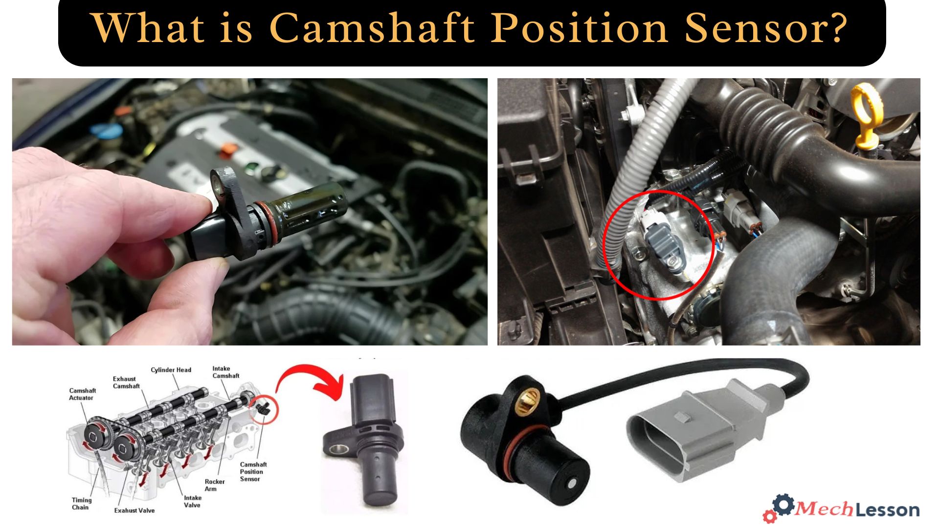
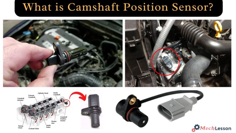
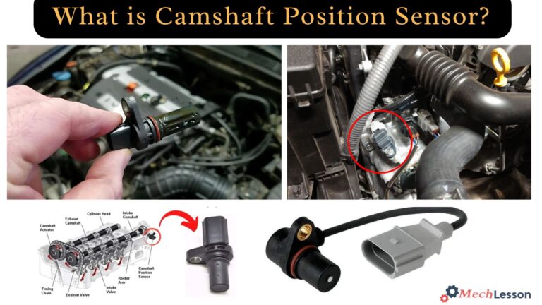
Source: mechlesson.com
Magnetic sensor
Usually has measurable coil resistance and can often be tested with an ohmmeter.
Hall-effect sensor
Typically requires voltage and signal testing instead of a simple resistance check.
Why resistance values vary
Different manufacturers use different sensor designs, wire gauges, and internal circuitry. As a result, resistance specifications can vary significantly even among similar engines.
Vehicle-specific design
Each engine platform may use a unique sensor specification.
What Does a Camshaft Position Sensor Do?
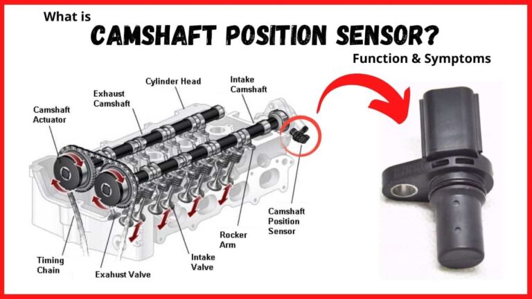
The camshaft position sensor monitors the position and rotational speed of the camshaft. The engine control module uses this information to manage fuel injection timing, ignition timing, and variable valve timing systems.
When the sensor sends incorrect information, the engine may experience poor performance, hard starting, misfires, rough idle, or a check engine light.
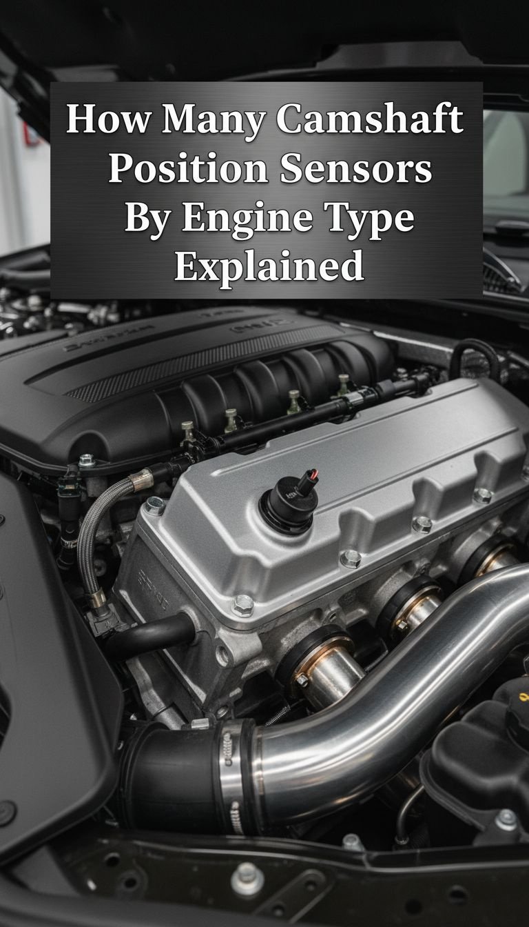
Source: ar.inspiredpencil.com
Fuel control
Helps determine when fuel injectors should operate.
Ignition timing
Supports accurate spark timing calculations.
Engine efficiency
Improves performance and emissions control.
Common symptoms of failure
A failing sensor can cause stalling, hesitation during acceleration, reduced fuel economy, and intermittent starting problems.
Check engine light
One of the most common warning signs.
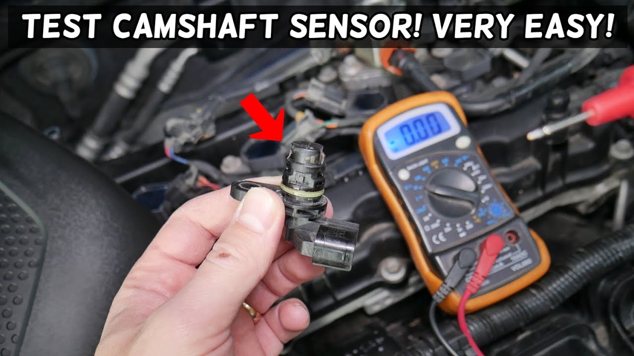
How to Test Camshaft Sensor Resistance with a Multimeter
Before testing, turn the ignition off and disconnect the sensor connector. Set the multimeter to the resistance setting and place the probes on the sensor terminals according to the service procedure.
Compare the measured resistance with the manufacturer’s specification. If the reading falls outside the approved range, further inspection or replacement may be necessary.
Source: storage.googleapis.com
Step 1
Locate and disconnect the sensor.
Step 2
Set the meter to measure ohms.
Step 3
Measure resistance across the correct terminals.
Step 4
Compare results with service specifications.
Signs of a successful test
A stable reading within specification indicates that the sensor winding is likely intact. Additional signal testing may still be required on modern systems.
Stable measurement
Consistent readings are generally preferable to fluctuating values.
Understanding Common Resistance Readings
The measured resistance can provide clues about sensor condition, but it should not be interpreted without context. Vehicle specifications remain the final authority.
The table below summarizes what common readings may indicate during basic diagnostics.
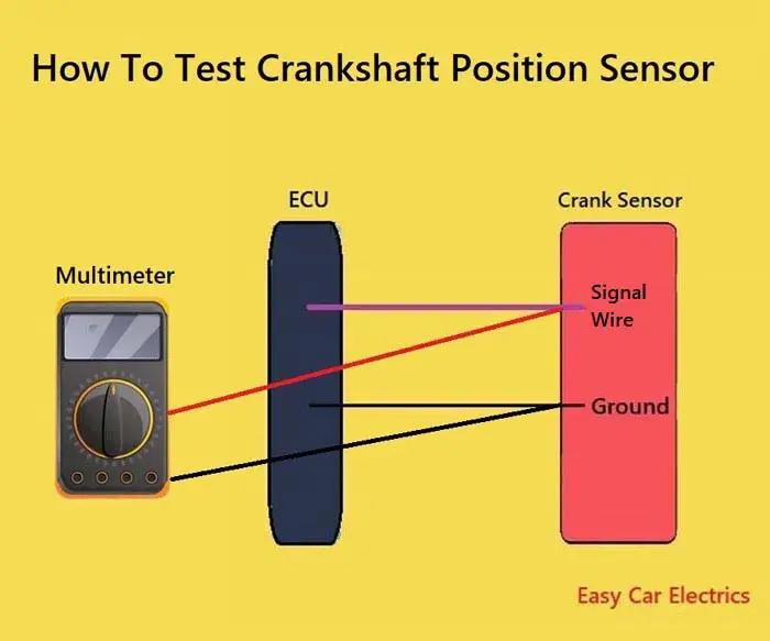
Source: storage.googleapis.com
0 ohms
May indicate a short circuit.
Infinite resistance
May indicate an open circuit.
Within specification
Suggests the sensor winding is likely intact.
Example interpretation table
A reading near specification is generally a positive sign, but a sensor can still fail under operating conditions. Voltage and waveform testing may be necessary.
Further diagnosis
Use scan tool data and signal testing when available.
Common Mistakes When Testing a Camshaft Sensor
One of the most common mistakes is assuming every sensor should have the same resistance value. Modern vehicles use different technologies that require different testing methods.
Another frequent error is testing a Hall-effect sensor only with an ohmmeter. These sensors often need power supply, ground, and signal verification for a complete diagnosis.
Source: carxplorer.com
Ignoring specifications
Always use the vehicle’s service information.
Testing with the connector attached
This can affect readings and lead to confusion.
Replacing parts too early
Wiring faults can mimic sensor failures.
When professional help is needed
If resistance, voltage, wiring, and scan tool checks produce conflicting results, professional diagnostic equipment can help isolate the fault.
Advanced testing
Oscilloscopes can reveal signal problems not visible with a standard multimeter.
Frequently Asked Questions
Q
Can a camshaft sensor have good resistance and still be bad?
Yes. A sensor can pass a resistance test but still fail when producing a live operating signal. Additional voltage or waveform testing may be required.
Q
What does infinite resistance mean on a camshaft sensor?
Infinite resistance often indicates an open circuit inside the sensor or a broken internal winding.
Q
Should a Hall-effect camshaft sensor be tested in ohms?
Hall-effect sensors are usually tested by checking power, ground, and signal output rather than relying solely on resistance measurements.
Q
Can bad wiring cause camshaft sensor trouble codes?
Yes. Damaged wiring, corroded connectors, or poor grounds can create symptoms similar to a failed sensor.
Q
Do all vehicles use the same camshaft sensor resistance specification?
No. Resistance specifications vary by manufacturer, model, engine family, and sensor design.
✦ Wrapping Up
Conclusion
The answer to how many ohms should a camshaft sensor have depends on the specific sensor and vehicle. While many magnetic sensors fall within a range of several hundred to a few thousand ohms, there is no universal specification.
Accurate diagnosis requires comparing resistance readings with factory specifications and, when necessary, performing voltage and signal testing. This approach helps avoid unnecessary parts replacement and leads to a more reliable repair.
💡 Key Takeaway
Locate the factory resistance specification for your exact vehicle before judging whether a camshaft sensor is good or bad.
Ethan Brooks is an automotive writer at Auto News 7, covering car news, vehicle maintenance, new model updates, recalls, and practical buying guides. He focuses on clear, useful information that helps drivers understand their vehicles and make better ownership decisions.
Learn how to replace camshaft position sensor bank 1 with a clear step-by-step process, required tools, troubleshooting tips, and safety advice for DIY vehicle owners in the USA.
Learn whether a camshaft sensor needs to be programmed after replacement, when relearn procedures are required, common symptoms, troubleshooting steps, and what to expect during installation.
Learn how to check camshaft position sensor operation, wiring, voltage, and signal output. Follow this practical step-by-step guide to diagnose common camshaft sensor problems.