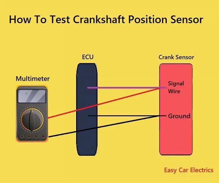
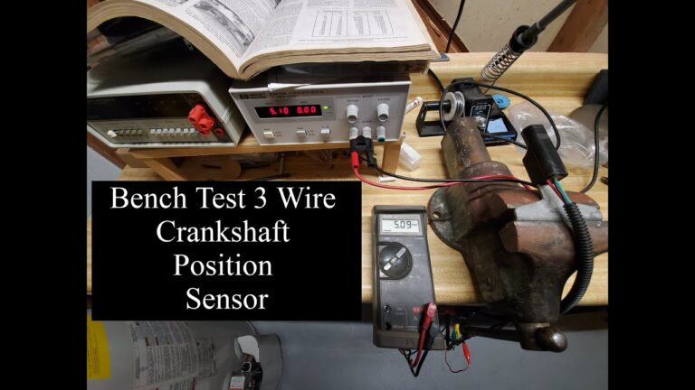
To test crankshaft and camshaft sensors correctly, first identify whether the sensor is a Hall-effect, inductive magnetic, or another design, then verify the connector, wiring, power supply, ground, and signal against the vehicle manufacturer’s specifications.
For drivers and DIY mechanics in the United States, a crank-no-start, intermittent stall, rough running condition, or check engine light can quickly lead to suspicion of the crankshaft position sensor or camshaft position sensor. These sensors are common across modern gasoline and diesel vehicles sold in the U.S., but testing them is not as simple as checking one universal resistance or voltage value. Designs and specifications vary considerably between manufacturers, engines, and model years.
The safest approach is to diagnose the complete circuit rather than immediately replacing the sensor. A digital multimeter can verify many power, ground, wiring, resistance, and basic signal conditions. A scan tool can show whether the engine control module is receiving useful information, while an oscilloscope gives the clearest view of the actual sensor waveform and crank-to-cam relationship.
This guide explains how to test crankshaft and camshaft sensors step by step, including how to distinguish common sensor types, what measurements are useful, what results mean, and when a sensor that appears electrically healthy may still have a mechanical or timing-related problem.
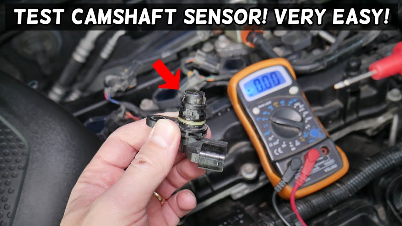
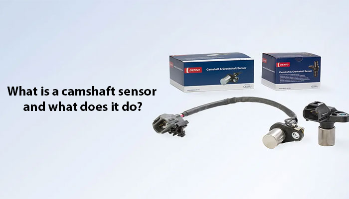
Source: triscan.dk
What Crankshaft and Camshaft Position Sensors Do
The crankshaft position sensor, commonly abbreviated CKP, tells the engine control module about crankshaft speed and position. The control module uses this information as a primary timing reference for functions such as ignition and fuel injection. If the CKP signal disappears or becomes unreliable, the engine may stall, fail to start, misfire, or store a diagnostic trouble code.
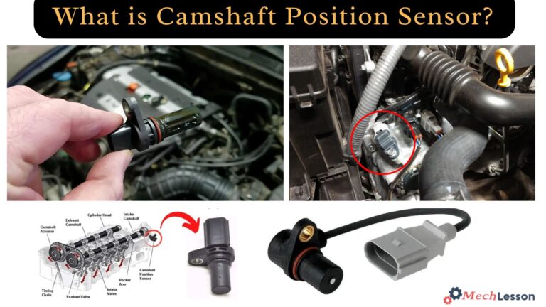
The camshaft position sensor, commonly abbreviated CMP, identifies camshaft position so the control module can determine where the engine is within its four-stroke cycle. This helps the system identify individual cylinders and coordinate sequential fuel injection, ignition strategy, and variable valve timing on engines equipped with those systems.
The two sensors therefore work together, but they are not interchangeable. A vehicle may have one crankshaft sensor and one or several camshaft sensors. Dual-overhead-cam engines, V-type engines, and engines with variable valve timing may use multiple CMP sensors.
A diagnostic trouble code mentioning a crankshaft or camshaft sensor does not automatically prove that the sensor itself has failed. Wiring faults, connector problems, damaged reluctor or trigger wheels, excessive sensor gaps, timing-chain problems, low system voltage, or control-module issues can produce similar symptoms.
Source: obdcode.org
CKP sensor role
Provides crankshaft speed and position information used as a fundamental engine timing reference.
CMP sensor role
Provides camshaft position information that helps the control module identify cylinder phase and coordinate engine functions.
Diagnosis matters
A sensor-related trouble code identifies a circuit or signal problem area, not necessarily a defective sensor.
Symptoms That May Lead You to Test These Sensors
Common complaints include extended cranking, a crank-no-start condition, intermittent stalling, rough running, misfires, poor acceleration, an illuminated check engine light, or an engine that starts only after cooling down. Symptoms vary because manufacturers use different fallback strategies when one of the signals is lost.
Crank-no-start
A missing CKP signal can prevent the engine control module from establishing the timing reference needed to operate the engine.
Intermittent stalling
A sensor, connector, or wire that fails when hot or vibrated may briefly interrupt its signal.
Check engine light
Sensor circuit, performance, or crank-to-cam correlation faults can trigger diagnostic trouble codes.
Before Testing, Identify the Sensor Type
Do not begin by randomly checking resistance across sensor terminals. First determine the sensor design using the factory wiring diagram, service information, or reliable component specifications for the exact vehicle. This matters because an ohmmeter may be appropriate for some passive inductive sensors but is not an appropriate universal test for powered electronic sensors.
Two-wire crankshaft sensors are often variable-reluctance or inductive sensors, but connector pin count alone should not be treated as absolute proof. Three-wire sensors are commonly Hall-effect devices with power, ground, and signal circuits, although other configurations exist. Modern vehicles can also use more complex sensor designs.
Inductive sensors contain a coil and magnetic element. As a toothed reluctor wheel moves past the sensor, the changing magnetic field creates an alternating voltage. Signal amplitude generally changes with rotational speed, which means a sensor may produce a weak voltage during slow cranking and a stronger signal as speed increases.
Hall-effect position sensors are powered electronic devices. A typical circuit includes a voltage supply, a ground, and a digital signal that switches between low and high states as the trigger wheel passes the sensing element. The exact supply and switching voltages must be confirmed from service information rather than assumed.
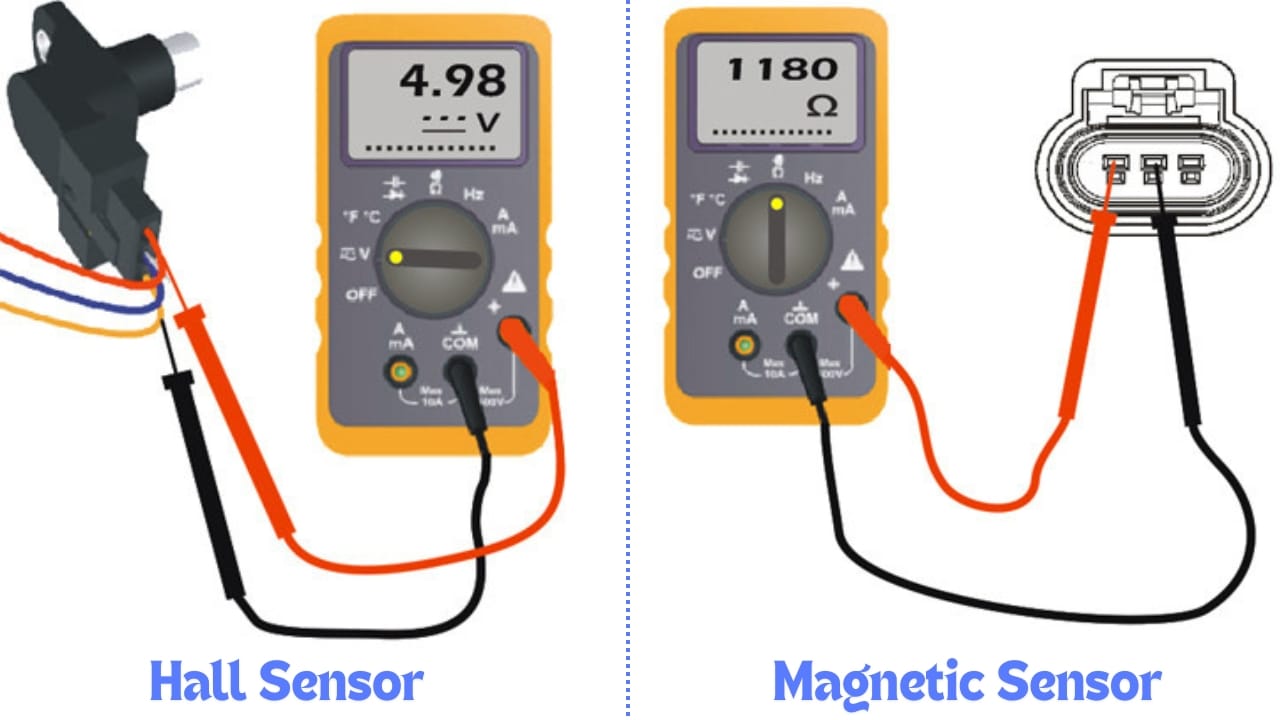
Source: midohiomobilemechanic.com
Inductive sensor
Usually generates an AC signal from the movement of a reluctor wheel and normally does not require the same external power arrangement as a Hall sensor.
Hall-effect sensor
Usually requires power and ground and produces a switched digital output.
Unknown sensor
Stop and obtain the correct wiring information before performing resistance or powered circuit tests.
Tools You May Need
A basic diagnosis can often begin with a scan tool and digital multimeter. An oscilloscope is preferable when you need to verify waveform quality, detect brief dropouts, compare crankshaft and camshaft timing, or evaluate a sensor that passes basic electrical tests but still causes an intermittent fault.
Digital multimeter
Useful for voltage, ground, continuity, resistance where appropriate, and basic AC signal checks.
OBD-II scan tool
Useful for retrieving trouble codes, viewing engine RPM during cranking, and checking applicable live data.
Oscilloscope
Shows signal shape, amplitude, frequency, switching, missing pulses, noise, and correlation between sensors.
Vehicle service information
Provides connector pin assignments, sensor type, expected values, test conditions, and waveform references.
Back-probe leads
Allow circuit measurements without forcing oversized probes into connector terminals.
How to Test Crankshaft and Camshaft Sensors Step by Step
Start with the least invasive checks and move toward electrical measurements only after you understand the circuit. This sequence reduces the risk of replacing a good sensor or accidentally damaging a connector or control-module circuit.
Park the vehicle on a level surface, apply the parking brake, select Park or Neutral as appropriate, and keep hands, clothing, meter leads, and tools away from belts, pulleys, fans, and other moving components. If a test requires cranking or running the engine, route test leads securely before operating the starter.
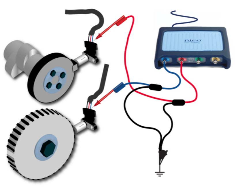
Source: pico-automotive.co.za
Step 1: Scan for trouble codes
Read stored, pending, and permanent codes when supported. Record them before clearing anything. CKP-related codes commonly fall in the P0335 family, while CMP-related faults commonly appear in P0340 and related families, but the exact definition should always be checked for the vehicle.
Step 2: Inspect the sensor and connector
Look for damaged insulation, loose terminals, bent pins, oil contamination, corrosion, water intrusion, broken connector locks, rubbing against brackets, or wiring near hot exhaust components.
Step 3: Inspect the mechanical trigger system
Where accessible, check for sensor damage, excessive debris, incorrect installation, damaged reluctor teeth, loose trigger wheels, or an excessive sensor-to-trigger gap.
Step 4: Verify battery condition
A weak battery can reduce cranking speed and system voltage, which may distort diagnosis. Correct obvious battery or starting-system problems before judging the sensor.
Step 5: Identify the circuit
Use the vehicle wiring diagram to identify power, ground, signal, reference, or paired inductive circuits before connecting the meter.
Step 6: Test power and ground when applicable
For a powered sensor, verify that the specified supply reaches the connector and that the ground circuit can provide a reliable return path.
Step 7: Check the signal
Back-probe the signal circuit and observe it during cranking or operation using the measurement method specified for that sensor.
Step 8: Compare the result with specifications
Do not judge the sensor using a generic internet voltage or resistance number when manufacturer data for the exact application is available.
Check Engine RPM During Cranking
One quick diagnostic clue is scan-tool engine speed while cranking. Because crankshaft position information is normally used to determine engine speed, an RPM value during cranking suggests that the control module is receiving some form of crankshaft speed information. However, this does not prove that the waveform is clean, correctly timed, or free of intermittent dropouts.
A zero RPM reading can point toward a missing CKP input, but it is still necessary to verify wiring, power where applicable, sensor output, and scan-tool data behavior before replacing the sensor.
How to Test a Hall-Effect Crankshaft or Camshaft Sensor
A Hall-effect sensor should normally be evaluated as a powered circuit. The most useful checks are the sensor supply, ground integrity, and switching signal. Resistance testing across an unidentified Hall sensor is not a recommended general diagnostic method.
With the ignition switched on and the sensor connected or disconnected as directed by the service procedure, identify the supply circuit using the wiring diagram. Many automotive Hall circuits use a regulated supply, often around 5 volts, but other designs exist. Treat the manufacturer’s specified voltage as the correct target.
Next verify the ground circuit. Measuring only an unloaded ground wire can miss excessive resistance that appears when current flows. Where appropriate, a voltage-drop test can provide a better indication of ground integrity. The allowable voltage drop depends on the circuit and manufacturer specifications.
Finally inspect the signal while the engine is cranking or running. A Hall-effect position sensor generally produces a digital switching pattern rather than the sine-wave pattern associated with a conventional inductive sensor. A digital multimeter may show a changing or averaged voltage, but it can update too slowly to display every transition.
An oscilloscope is therefore the better tool when you need to confirm the complete Hall signal. A healthy pattern should switch consistently without unexplained dropouts or excessive noise, and its shape should match the expected trigger-wheel design.
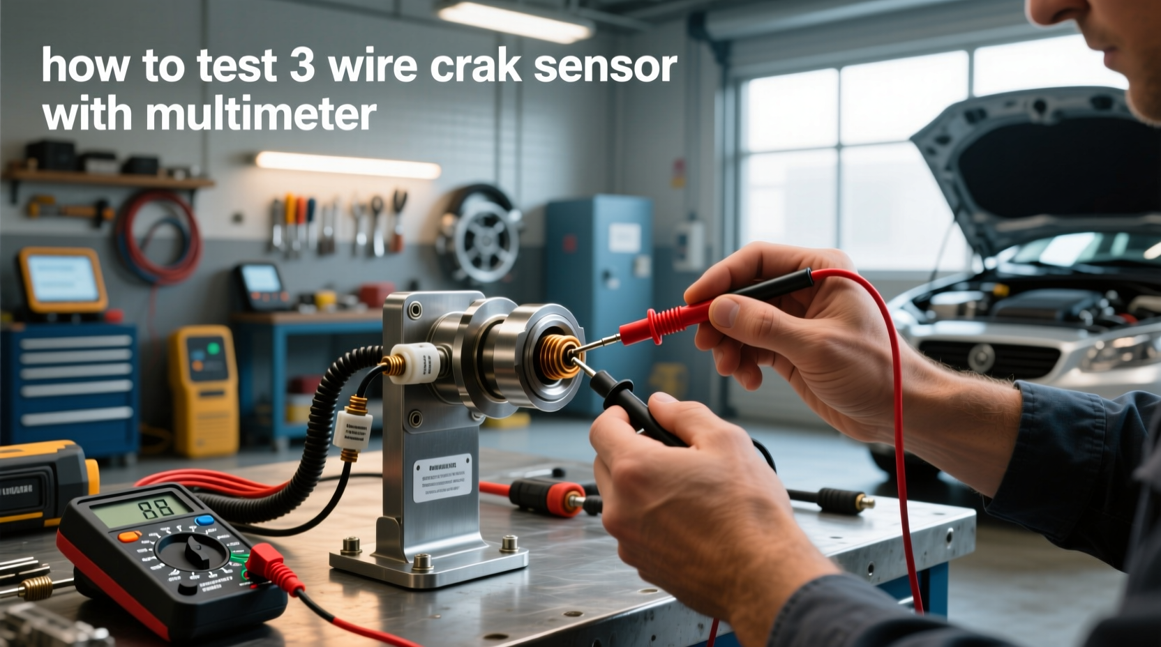
Source: carinterior.alibaba.com
Power present but no signal
Verify ground, wiring continuity, connector condition, trigger-wheel movement, and the sensor itself.
No power supply
Do not replace the sensor yet. Diagnose the supply circuit, shared reference circuit, fuse where applicable, wiring, or control-module output.
Signal stuck high or low
A sensor fault is possible, but a shorted signal wire, missing ground, supply problem, excessive air gap, or trigger-wheel problem may produce a similar result.
Signal drops out when hot
Repeat the test under the conditions that reproduce the fault while monitoring the waveform and associated circuits.
Why a Multimeter Can Miss a Hall Sensor Problem
A multimeter is designed primarily to display numerical measurements rather than a detailed high-speed waveform. If the sensor switches repeatedly between low and high voltage, the meter may display an average or rapidly changing value. That can confirm activity but may hide a single missing pulse, distorted edge, or momentary interruption.
If the vehicle has an intermittent stall, synchronization code, or recurring sensor code despite normal basic voltage checks, waveform testing is the logical next step.
How to Test an Inductive Crankshaft or Camshaft Sensor
A conventional inductive position sensor generates voltage as the reluctor or trigger wheel moves past its magnetic core. Testing therefore focuses on the sensor coil, circuit integrity, and generated AC waveform. Confirm that the sensor is actually an inductive design before using resistance measurements.
With the ignition off and the circuit isolated as required by the service manual, measure resistance across the appropriate sensor terminals. Some inductive crankshaft sensors may fall within a range of a few hundred to around one thousand ohms, but that is only a general example. The correct specification for the exact sensor takes priority.
A reading near zero resistance can indicate a shorted winding, while an open-circuit or extremely high reading can indicate a broken winding. However, a resistance value within specification does not prove that the sensor produces a correct signal during cranking or when hot.
To perform a basic output test, set a suitable meter to AC voltage and measure across the sensor signal terminals while cranking the engine, following the manufacturer’s procedure. The sensor should generate an alternating voltage as the reluctor wheel moves past it. Because output depends on design, cranking speed, air gap, and trigger-wheel geometry, use the specified minimum output rather than a universal voltage target.
An oscilloscope provides a much better view. A typical variable-reluctance sensor produces an alternating waveform whose frequency follows rotational speed. Missing-tooth trigger wheels intentionally produce a recognizable reference gap, so a gap in the waveform is not automatically a sensor fault.
Source: artofit.org
Open resistance reading
May indicate a broken sensor winding, disconnected conductor, or poor terminal contact.
Very low resistance
May indicate an internal short, but compare the measurement with the specified range before deciding.
Weak generated signal
Possible causes include a damaged sensor, low cranking speed, excessive air gap, trigger-wheel damage, or wiring problems.
Irregular waveform
Inspect for damaged or contaminated trigger components, excessive movement, wiring interference, and mechanical defects.
Do Not Rely on Resistance Alone
A coil can have normal resistance while producing an inadequate signal under real operating conditions. Temperature-related failures can also disappear after the engine cools. When symptoms occur only when hot, monitor the sensor output as the engine reaches the temperature at which the problem normally occurs.
How to Test Sensor Wiring, Power, and Ground
Many position-sensor problems originate outside the sensor. Before installing a replacement, confirm that the wiring between the sensor and control module is intact and that the circuit is not shorted to power, ground, or another wire.
Disconnecting the battery is not automatically required for every diagnostic measurement, and doing so can erase learned values or stored information on some vehicles. Follow the service procedure for the exact test. Resistance and continuity checks should be performed only on de-energized circuits and with sensitive control modules isolated where specified.
For continuity testing, disconnect the relevant connectors as directed by the wiring diagram and measure the resistance of the wire from one end to the other. A low reading typically indicates continuity, but connector and harness specifications determine what is acceptable.
A wire can still pass a basic continuity test and fail in service. A nearly broken conductor may make contact when stationary but open when the harness moves. If an intermittent fault is suspected, monitor the circuit while gently moving accessible sections of the harness and connectors. Avoid pulling or damaging wires.
Visual inspection is particularly valuable around the front or rear of the engine, transmission bellhousing, cylinder head, exhaust components, accessory brackets, and harness retaining clips because sensor wires may be exposed to heat, vibration, oil, road debris, or abrasion.
Inspect connector terminals
Look for terminals that are bent, spread, recessed, corroded, wet, contaminated, or unable to grip the mating pin securely.
Check continuity
Measure only after de-energizing and isolating the circuit as required by the service information.
Check for shorts
Verify that the signal wire is not unintentionally connected to ground, battery voltage, or another circuit.
Test under fault conditions
Intermittent problems may require monitoring while the engine is hot or while the harness is gently moved.
Avoid Damaging Connector Terminals
Do not force standard multimeter probes into small connector cavities. Oversized probes can spread terminals and create a new intermittent connection. Use suitable back-probe pins, breakout leads, or manufacturer-approved test adapters whenever possible.
Using an Oscilloscope for a More Reliable Diagnosis
An oscilloscope turns sensor voltage over time into a visible waveform. This allows you to evaluate details that a multimeter cannot show clearly, including individual pulses, signal amplitude, noise, missing transitions, changes with RPM, and intermittent dropouts.
For a Hall-effect sensor, the scope normally displays a switching waveform whose high and low states correspond to the trigger pattern. For a conventional inductive sensor, the scope normally displays an alternating waveform. The exact shape depends on sensor and trigger-wheel design.
Oscilloscope testing becomes particularly useful when the vehicle sets correlation or synchronization codes. By displaying the crankshaft and camshaft signals at the same time, a technician can compare their relative positions. This can reveal a timing relationship that differs from a known-good waveform.
However, an abnormal crank-to-cam relationship does not automatically mean either sensor is defective. A stretched or incorrectly installed timing chain, slipped or damaged trigger wheel, variable-valve-timing problem, damaged pulley, or other mechanical timing issue can shift the relationship while both sensors continue generating signals.
Source: pico-automotive.co.za
Missing pulses
May indicate an electrical interruption, trigger-wheel defect, or an intentional reference feature depending on the system design.
Noise or distortion
Can result from circuit interference, poor connections, wiring problems, incorrect test setup, or mechanical issues.
Crank-to-cam shift
Can indicate a mechanical timing or trigger-reference problem rather than a failed sensor.
Heat-related dropout
Monitoring continuously as the engine warms can expose a sensor or circuit that fails only at operating temperature.
Compare With a Known-Good Reference
Waveforms should be compared with service information or a verified known-good example for the same engine configuration whenever possible. Counting pulses or judging synchronization without knowing the intended trigger pattern can lead to an incorrect diagnosis.
How to Interpret Your Test Results
The strongest diagnosis combines several pieces of evidence. A sensor should not normally be condemned because of one isolated resistance reading or one trouble code. Consider what the control module reports, what the circuit measurements show, and whether the signal remains correct under the conditions that produce the complaint.
For example, a Hall sensor that has correct power and ground but never switches despite a rotating trigger wheel may be defective. However, the same symptom could occur if the signal wire is shorted or the trigger wheel is damaged. Likewise, an inductive sensor with acceptable resistance but almost no generated signal may have excessive air gap, low cranking speed, a damaged trigger wheel, or an internal problem that resistance testing does not expose.
No supply voltage on a powered sensor
Diagnose the vehicle circuit before replacing the sensor.
Good power and ground but no output
Check trigger movement, air gap, signal wiring, and sensor operation.
Good sensor output at the sensor but not at the control module
Suspect an open, short, high-resistance connection, or terminal problem in the harness.
Good individual signals but correlation fault remains
Repeat signal and circuit testing at the temperature where the symptom occurs.
Signs of a Successful Test
A successful diagnosis establishes that the sensor receives the correct electrical support when required, produces the expected output, sends that output through intact wiring to the control module, and maintains a valid relationship with the engine’s mechanical timing.
If all of those checks are normal, replacing the sensor simply because its name appears in a trouble-code description is unlikely to solve a fault caused elsewhere.
Common Testing Mistakes to Avoid
The most common mistake is treating every crankshaft or camshaft sensor as though it uses the same circuit. Testing procedures that are correct for a passive inductive sensor can be inappropriate for a powered Hall-effect sensor.
Another mistake is replacing a sensor before inspecting its connector and wiring. Heat-damaged insulation, oil contamination, corrosion, loose pins, or a broken conductor can create symptoms almost identical to a failed sensor.
Avoid piercing wire insulation unless the vehicle manufacturer’s diagnostic procedure specifically permits it and the puncture can be repaired correctly. Moisture can later enter the conductor through an improperly sealed hole.
Do not work around rotating engine components with loose clothing, jewelry, unsecured hair, or dangling meter leads. If safe access is not possible while the engine runs, use appropriate remote test leads or have the diagnosis performed professionally.
Using universal resistance values
Sensor specifications vary, so generic readings should not replace application-specific service data.
Testing an unknown sensor with an ohmmeter
Identify the design first because resistance testing is not appropriate for every electronic sensor.
Replacing parts from a code alone
A code can be caused by wiring, mechanical timing, trigger components, voltage problems, or the sensor.
Ignoring cranking speed
Slow cranking can alter generated signals and complicate diagnosis.
Ignoring intermittent conditions
A sensor that works cold may fail after heat soak or vibration.
When to Stop DIY Testing
Professional diagnosis is reasonable when the sensor is difficult to access, the circuit uses unfamiliar technology, the repair requires working close to moving components, the vehicle repeatedly sets crank-to-cam correlation codes, or basic tests point toward mechanical timing. Timing-chain and internal engine work can cause severe engine damage if performed incorrectly on an interference engine.
Crankshaft Sensor vs Camshaft Sensor Test Comparison
The overall diagnostic process is similar for both sensors, but the role of each signal changes how the results are interpreted. The crankshaft sensor generally provides the fundamental engine speed and position reference, while the camshaft sensor provides phase information needed to identify the engine cycle and individual cylinders.
Use the following comparison as a diagnostic framework rather than as a source of universal electrical specifications.
Crankshaft sensor first check
Check trouble codes, observe RPM during cranking, inspect the circuit, and verify a valid CKP signal.
Camshaft sensor first check
Check trouble codes and live data, then verify power, ground, wiring, and CMP output according to sensor type.
Both signals appear normal
If correlation codes remain, compare their timing relationship and inspect mechanical timing and trigger components.
Intermittent fault
Capture live data or waveforms while recreating the temperature, vibration, and operating conditions associated with the complaint.
What to Do If the Sensor Passes the Test but the Problem Remains
A passing sensor test should redirect the diagnosis rather than end it. Verify that the signal actually reaches the engine control module and that it remains stable during the fault. Then investigate related components and mechanical conditions.
Crankshaft and camshaft signals depend on physical trigger components. A damaged reluctor, loose tone wheel, excessive crankshaft movement, incorrect sensor mounting, or excessive sensor gap can create a poor signal even when the electronic sensor itself is capable of operating normally.
Crank-to-cam correlation faults deserve special attention because they can originate from mechanical valve timing. A worn or stretched timing chain, incorrect belt or chain installation, faulty tensioner, damaged sprocket, or variable-valve-timing system problem can change the relationship between the two signals.
If the vehicle has recently undergone engine, timing, transmission, flywheel, cylinder-head, or camshaft work, consider whether the symptom began immediately afterward. That timing can provide an important diagnostic clue without proving which component is responsible.
Inspect trigger wheels
Check for damage, movement, contamination, incorrect indexing, or installation problems where accessible.
Verify mechanical timing
Correlation faults can result from a timing belt, timing chain, sprocket, tensioner, or variable-valve-timing problem.
Check the complete harness
Confirm that a valid sensor signal reaches the control-module connector rather than existing only at the sensor.
Check applicable technical information
Manufacturer service information may identify known diagnostic procedures, revised components, relearn requirements, or application-specific tests.
Frequently Asked Questions About How to Test Crankshaft and Camshaft Sensors
Q
Can you test a crankshaft sensor with a multimeter?
Yes, a multimeter can test several aspects of many crankshaft sensor circuits. Depending on sensor design, you may be able to check resistance, generated AC voltage, supply voltage, ground, continuity, or basic signal activity.
The correct method depends on whether the CKP sensor is inductive, Hall-effect, or another design. A multimeter also cannot display waveform details as effectively as an oscilloscope.
Q
Can you test a camshaft position sensor with a multimeter?
Yes. For a typical powered Hall-effect camshaft sensor, a multimeter can help verify power, ground, and basic signal behavior. The exact connector pins and expected voltages must come from service information for the vehicle.
If the meter readings appear normal but the code or symptom remains, an oscilloscope can reveal signal dropouts, abnormal switching, or synchronization problems that a standard meter may miss.
Q
How many ohms should a crankshaft position sensor have?
There is no universal resistance specification for all crankshaft sensors. Some conventional inductive sensors may measure within a few hundred to around one thousand ohms, but other sensors use different specifications and some electronic sensors should not be diagnosed by resistance testing.
Use the specification for the exact year, make, model, engine, and sensor part number whenever possible.
Q
Does a bad crankshaft sensor always set a trouble code?
No. An intermittent signal may cause stalling or starting problems without immediately producing the code a technician expects. Code-setting logic varies by manufacturer, and an intermittent fault may need to occur for a particular duration or operating condition before a code is stored.
Stored, pending, and manufacturer-specific codes should therefore be considered alongside live data and direct electrical testing.
Q
Can a bad timing chain look like a bad camshaft or crankshaft sensor?
Yes. If valve timing shifts, the control module may detect an incorrect relationship between the crankshaft and camshaft signals even though both sensors are generating electrical outputs. A stretched chain, slipped timing, faulty tensioner, variable-valve-timing problem, or incorrectly indexed trigger component can contribute to correlation faults.
When both individual sensor waveforms appear healthy but their relationship is incorrect, mechanical timing should be investigated.
✦ Wrapping Up
Conclusion
Learning how to test crankshaft and camshaft sensors is mainly about following the circuit logically rather than searching for one universal meter reading. Start by retrieving trouble codes and inspecting the wiring, connector, sensor mounting, and surrounding components. Then identify the exact sensor technology before choosing a resistance, voltage, or waveform test.
For an inductive sensor, resistance and generated AC voltage can provide useful clues when those tests are approved for the application. For a Hall-effect sensor, concentrate on supply voltage, ground, and the switching signal. If basic measurements do not explain the fault, an oscilloscope can reveal missing pulses, intermittent dropouts, waveform distortion, and crank-to-cam synchronization problems.
Most importantly, do not assume that a sensor-related code means the sensor needs replacement. Confirm the electrical circuit and consider mechanical timing, trigger-wheel condition, sensor gap, cranking speed, and intermittent wiring faults before buying parts.
💡 Key Takeaway
Retrieve the codes, identify the sensor type from reliable service information, inspect the circuit, verify power and ground where applicable, test the signal under actual cranking or running conditions, and replace the sensor only after the evidence points to the sensor itself.
Ethan Brooks is an automotive writer at Auto News 7, covering car news, vehicle maintenance, new model updates, recalls, and practical buying guides. He focuses on clear, useful information that helps drivers understand their vehicles and make better ownership decisions.
Learn how to check camshaft position sensor operation, wiring, voltage, and signal output. Follow this practical step-by-step guide to diagnose common camshaft sensor problems.
Learn how to replace camshaft position sensor components with a detailed step-by-step guide, tools list, troubleshooting tips, safety advice, and common mistakes to avoid.