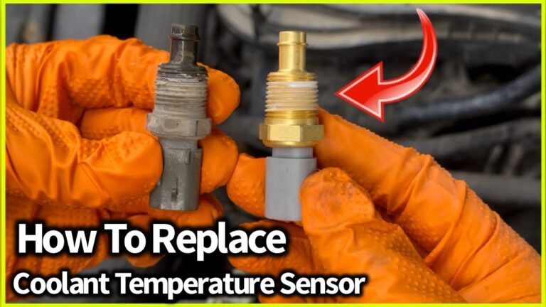
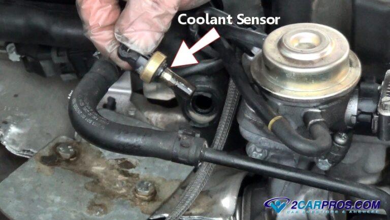
To change a coolant temperature sensor harness, first confirm that the harness or connector is actually faulty, disconnect the battery when appropriate, identify each wire before cutting, splice the replacement pigtail using the correct terminals and weather-resistant connections, secure the harness away from heat and moving parts, and then verify the ECT signal with a scan tool or the vehicle manufacturer’s diagnostic procedure.
For drivers and DIY mechanics in the United States, a damaged engine coolant temperature sensor harness can cause much more than an annoying Check Engine light. The engine control module uses the coolant temperature sensor signal to help manage fuel delivery and other engine functions, while some vehicles also use coolant temperature information for cooling-fan control and the instrument cluster. A poor connection, broken conductor, corrosion, or short circuit can therefore produce symptoms that resemble a failed sensor.
The repair is usually more involved than simply unplugging and replacing a sensor. The exact connector, terminal arrangement, wire gauge, splice method, and routing depend on the vehicle. Before cutting any wires, use the factory service information for the specific year, make, model, engine, and market. Diagnostic information for OBD-II vehicles shows that ECT circuit faults can be associated with open, shorted, intermittent, or out-of-range conditions, so replacing the harness without testing can result in an unnecessary repair.
Source: fity.club
What Is a Coolant Temperature Sensor Harness?
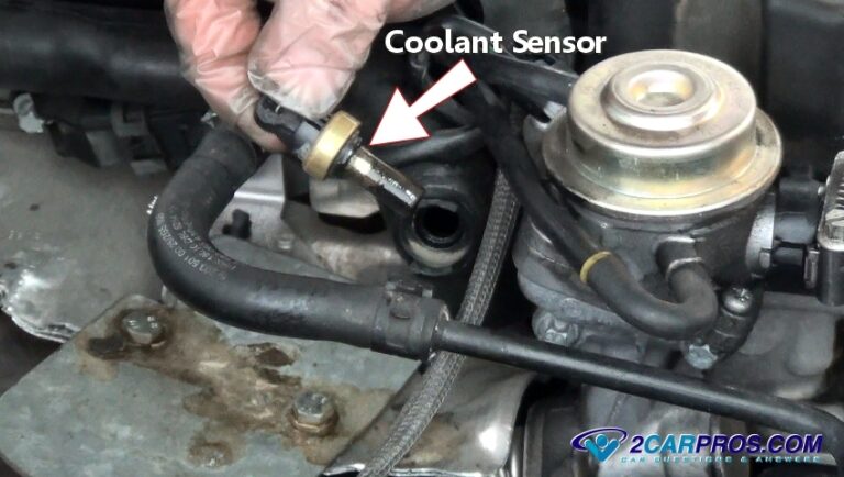
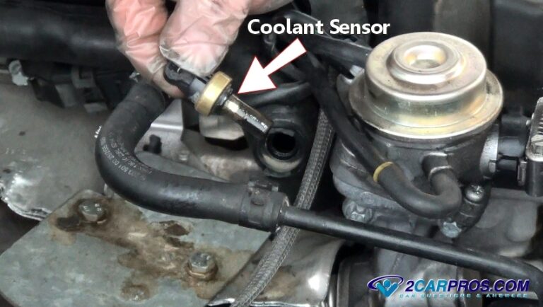
The coolant temperature sensor harness is the wiring and connector assembly that electrically links the engine coolant temperature sensor to the vehicle’s engine control module or another control circuit. On many modern vehicles, the ECT sensor is a thermistor whose resistance changes with temperature. The control module interprets the resulting electrical signal as coolant temperature.
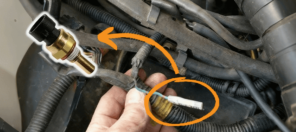
The term harness can refer to a short sensor pigtail with a connector or to a longer section of vehicle wiring. If only the connector and a few inches of wire are damaged, a replacement pigtail is often the practical repair. If damage extends farther into the main engine harness, the repair may require additional wiring work or professional diagnosis.
Source: freepik.com
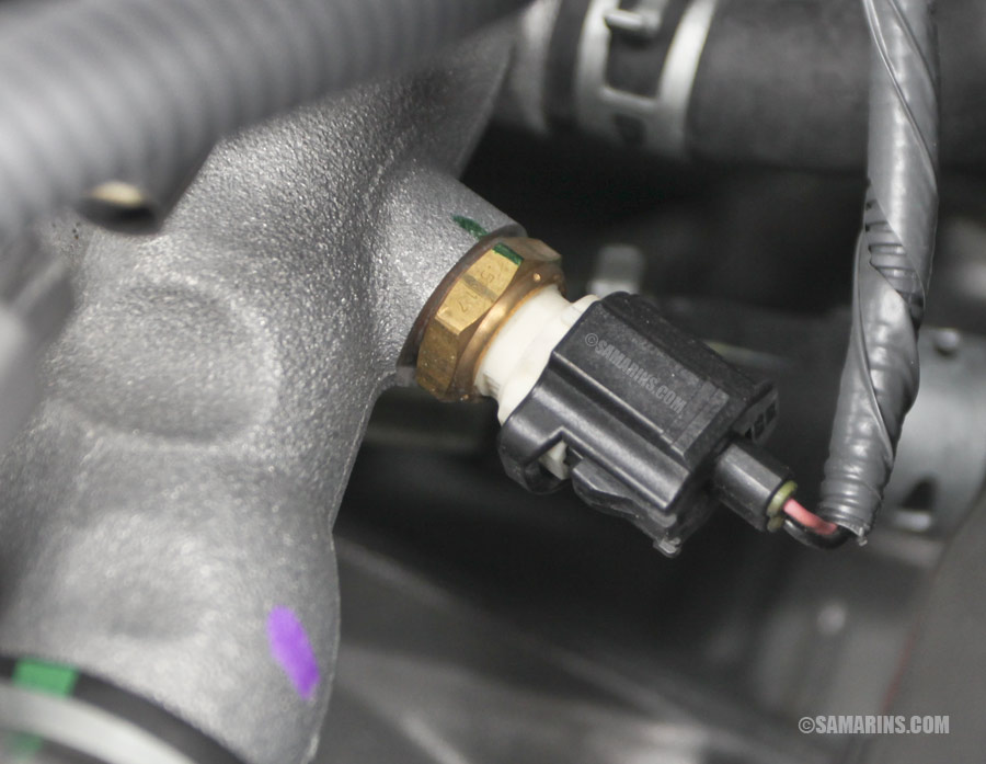
Connector
The connector locks onto the ECT sensor and contains terminals that make the electrical connection.
Pigtail
A pigtail is a short replacement connector assembly with attached wires that can be spliced into the existing harness.
Circuit wires
Depending on the vehicle, the ECT circuit may include a signal circuit and a sensor ground or return circuit, with exact wiring determined by the manufacturer’s design.
Why the Harness Can Fail
Common causes include heat exposure, insulation becoming brittle, vibration, oil or coolant contamination, corrosion at terminals, water intrusion, improper previous repairs, and physical strain on the connector. Older connectors can also become fragile from repeated thermal cycling.
A damaged connector does not automatically mean the entire wiring harness needs replacement. If the connector is loose, corroded, cracked, or has damaged terminals while the wiring remains sound, replacing the connector or pigtail may be sufficient.
Heat damage
Wiring routed too close to exhaust components can become brittle or develop damaged insulation.
Corrosion
Moisture or coolant contamination can corrode terminals and increase electrical resistance or interrupt the circuit.
Mechanical damage
Vibration, rubbing, or pulling can break conductors inside otherwise intact insulation.
Signs the Coolant Temperature Sensor Harness May Be Bad
An ECT wiring problem can produce an incorrect or unstable coolant temperature signal. Depending on the vehicle’s control strategy, symptoms can include a Check Engine light, difficult starting, poor fuel economy, abnormal idle behavior, incorrect temperature information, or cooling-fan operation that does not match engine temperature.
OBD-II diagnostic codes can provide useful clues. P0115 relates to the ECT circuit, while P0117, P0118, and P0119 identify specific low-input, high-input, and intermittent ECT circuit conditions. These codes do not by themselves prove that the harness is defective; the sensor, connector, wiring, and control module still need to be checked.
Source: fridayparts.com
P0115
Engine coolant temperature circuit malfunction. The underlying cause may be the sensor, wiring, connector, or related control circuitry.
P0117
ECT circuit low input. A shorted circuit or other electrical fault can cause this condition.
P0118
ECT circuit high input. An open circuit, disconnected connector, or related wiring fault can cause this condition.
P0119
ECT circuit intermittent. An unstable connection or intermittent wiring fault should be considered.
Inspect Before You Replace
Start with a visual inspection of the connector and the first several inches of wiring. Look for broken locking tabs, loose terminals, green or white corrosion, damaged insulation, exposed copper, stretched wires, and evidence of contact with hot or moving components. If the connector is clean and the wiring appears intact, electrical testing should come before cutting the harness.
A scan tool can also help distinguish a sensor problem from a wiring problem. On a cold engine that has been sitting long enough to reach ambient temperature, the ECT reading should be reasonable for the surrounding conditions. As the engine warms, the displayed coolant temperature should change in a logical direction. An implausible fixed reading or sudden jump can indicate a circuit or sensor problem.
Do not assume the sensor is bad
A wiring fault can create the same general symptoms as a failed ECT sensor.
Check connector terminals
Bent, spread, recessed, corroded, or loose terminals can interrupt the circuit even when the wires look normal.
Tools and Parts Needed to Change the Harness
The exact tools depend on the vehicle and the type of harness repair. A connector replacement normally requires fewer tools than repairing a damaged section of the engine wiring harness. Obtain the correct replacement pigtail or connector before cutting the original wiring.
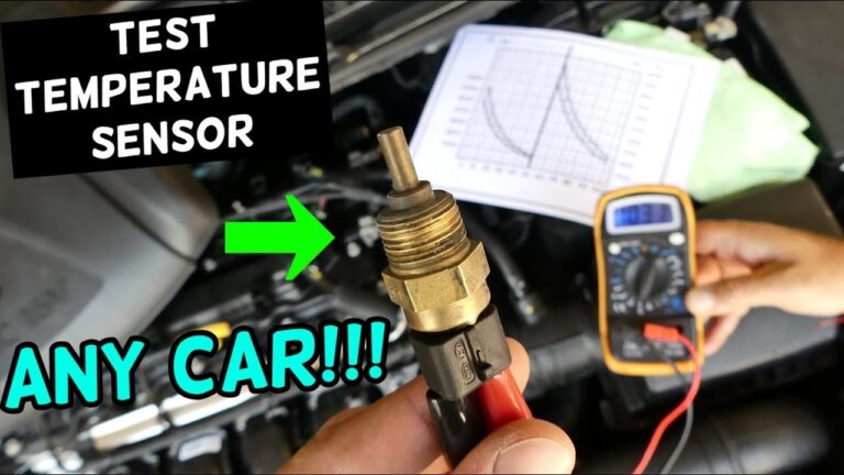
For many repairs, the most useful diagnostic tool is a digital multimeter or scan tool. The multimeter can help check continuity and electrical conditions when used according to the manufacturer’s circuit test procedure. A scan tool can show live ECT data and stored diagnostic trouble codes.
Source: detroitchinatown.org
Replacement ECT pigtail or connector
Use a connector designed for the exact sensor and vehicle application, with the correct terminal configuration.
Digital multimeter
Useful for continuity, resistance, voltage, and circuit checks when the manufacturer’s procedure specifies the test.
Wire repair supplies
Use appropriately sized automotive wire and a suitable sealed splice method or approved crimp connection.
Wire strippers and cutters
Use tools that can remove insulation without damaging the copper conductors.
Heat-shrink tubing
Use automotive-grade heat-shrink material suitable for the repaired wiring and its location.
Basic hand tools
A small pick or terminal tool may be needed to release connector locks or retainers without damaging the connector.
Prerequisites Before Starting
Park the vehicle securely, switch the ignition off, and allow the engine and cooling system to cool completely. Hot coolant can cause serious burns and the cooling system may remain pressurized after the engine is shut off.
Identify the correct ECT sensor and wiring using vehicle-specific service information. Some vehicles have more than one coolant temperature-related sensor or switch, and the component used by the engine control module may not be the same component used by the gauge or another system.
Confirm the application
Verify the year, make, model, engine, transmission where relevant, and connector configuration before purchasing a pigtail.
Record the original wiring
Photograph the connector and wire positions before removing or cutting anything.
How to Change a Coolant Temperature Sensor Harness
The safest general method is to diagnose the circuit, remove the damaged connector or wiring section, splice the replacement pigtail using the manufacturer’s wire identification, secure the repair, and then verify the ECT signal. Do not use a generic wire order because connector pinouts vary by vehicle.
Source: YouTube > rehma6b0
Step 1: Let the engine cool
Work only after the engine and cooling system have cooled sufficiently to eliminate the immediate risk of hot coolant or a pressurized cooling system.
Step 2: Disconnect power as specified
Follow the vehicle manufacturer’s procedure for battery disconnection. Some vehicles have electrical systems or stored settings that require specific precautions.
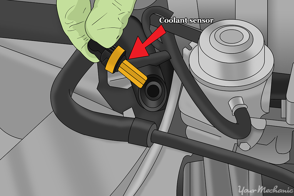
Step 3: Locate the ECT connector
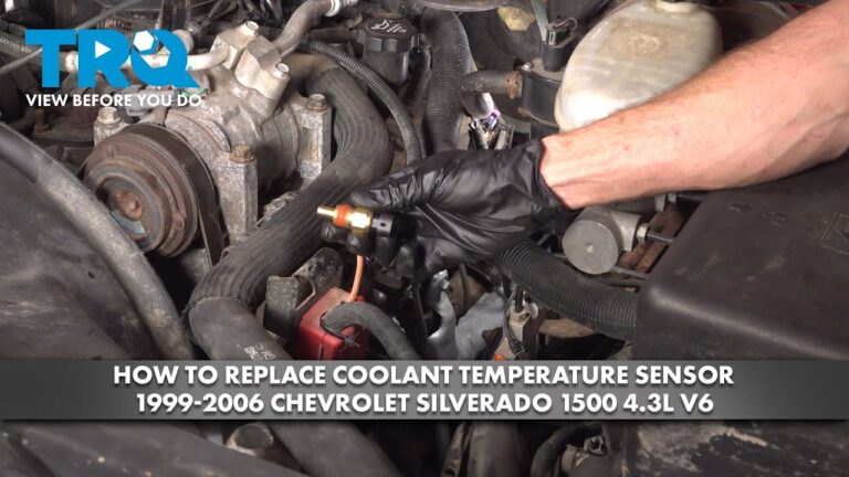
Find the engine coolant temperature sensor and trace its wiring far enough to determine whether the damage is limited to the connector or extends into the harness.
Step 4: Inspect and test the circuit
Check for corrosion, damaged terminals, broken conductors, short circuits, and poor connections. Compare electrical measurements with the vehicle-specific service specifications.
Step 5: Photograph and identify the wires
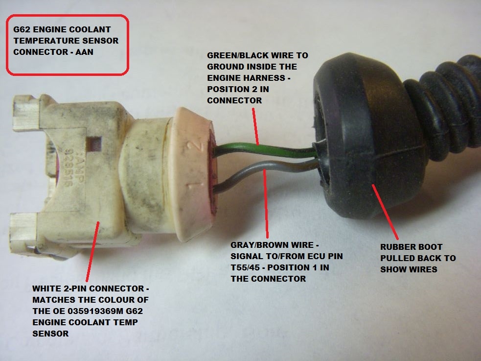
Before cutting the old connector, document the wire position, terminal position, colors, and connector orientation. Do not rely on color alone if the service information identifies circuits by terminal number.
Step 6: Remove the damaged pigtail
Cut the damaged wiring at a clean section of healthy conductor. Leave enough length to make a secure repair without placing the new splice under tension.
Step 7: Prepare the replacement pigtail
Compare the replacement connector with the original and confirm the terminal positions. Match each circuit according to the factory wiring information rather than simply matching connector appearance.
Step 8: Make the splices
Strip only the required amount of insulation and make electrically and mechanically secure connections using an approved automotive wiring repair method. Seal the repair against moisture and corrosion.
Step 9: Protect and route the harness
Restore loom, clips, retainers, and protective covering as needed. Keep the wiring away from exhaust components, belts, pulleys, fans, sharp edges, and other sources of heat or abrasion.
Step 10: Reconnect the ECT sensor
Push the replacement connector onto the sensor until its locking mechanism engages. Never force a connector that does not align correctly.
Step 11: Restore the electrical system
Reconnect the battery or other disconnected electrical components according to the vehicle’s service procedure.
Step 12: Verify operation
Use a scan tool or the manufacturer’s prescribed diagnostic procedure to confirm a plausible ECT signal. Clear diagnostic codes only after documenting them, then check whether the fault returns.
How to Make a Reliable Harness Splice
A harness repair should be both electrically sound and mechanically supported. The connection should not depend on a loose twist of wires or ordinary household electrical tape. Use a repair method approved for automotive wiring and appropriate for the location’s heat, moisture, vibration, and chemical exposure.
When a service manual specifies a particular terminal repair, crimp type, splice sleeve, solder procedure, or heat-shrink material, follow that procedure. Different manufacturers can specify different repair methods, and a generic technique should not override a documented factory repair instruction.
Match the wire size
The replacement conductor should be appropriate for the original circuit and the manufacturer’s wiring specifications.
Protect the connection
Seal the splice against moisture and provide strain relief so vibration does not transfer directly into the electrical joint.
Avoid excessive exposed conductor
Excess exposed copper can increase the chance of corrosion or an accidental short circuit.
How to Verify the Repair
A successful repair should produce a stable electrical connection and a plausible coolant temperature reading. With the engine cold, compare the scan-tool ECT value with ambient conditions and other relevant temperature readings when the manufacturer’s diagnostic procedure calls for that comparison. As the engine warms, the ECT reading should change progressively rather than remain fixed or jump erratically.
If the original code returns immediately, do not assume the new pigtail failed. Recheck terminal engagement, wire routing, splice integrity, circuit continuity, reference voltage or ground as applicable, and the sensor itself. Follow the vehicle-specific pinpoint test before replacing additional parts.
Stable connector
The connector should lock onto the sensor and remain secure when the harness is gently positioned.
Plausible live data
ECT data should respond logically as the engine changes from cold toward normal operating temperature.
No recurring fault
After completing the prescribed drive or monitor conditions, the repaired circuit should not immediately reproduce the same fault.
Common Mistakes When Replacing an ECT Sensor Harness
Most avoidable harness-repair problems come from diagnosing too quickly, mixing up connector terminals, making an inadequately protected splice, or routing the repaired wires where heat or vibration can damage them again. Taking a few minutes to document the original circuit can prevent an expensive wiring mistake.
Source: storage.googleapis.com
Replacing the harness without testing
A defective sensor, thermostat, connector terminal, or unrelated cooling-system problem can create similar symptoms. Diagnose the circuit before cutting wires.
Matching wires by color alone
Wire colors can vary by vehicle and circuit. Use terminal numbers and the factory wiring diagram whenever available.
Pulling on the connector
Release the locking tab or secondary lock before separating the connector. Excessive force can damage the connector or terminal.
Leaving the splice exposed
An unprotected splice can corrode or become mechanically weak, especially in the engine compartment.
Routing the new wires too close to heat
A replacement harness can fail again if it contacts the exhaust manifold, turbocharger components, or another high-temperature surface.
Ignoring low coolant
Low coolant can affect sensor readings and may indicate a separate cooling-system leak that must be addressed.
When You Should Stop and Get Professional Help
Stop the repair if the wiring diagram cannot be identified confidently, several circuits are damaged, the connector is part of a larger sealed harness that requires specialized terminal tooling, or electrical measurements do not agree with the manufacturer’s diagnostic procedure. Professional diagnosis is also appropriate if the vehicle is overheating or losing coolant because the harness repair does not address mechanical cooling-system faults.
A wiring repair should never be used to mask an overheating problem. If the temperature warning light is on, the gauge indicates overheating, steam is present, or coolant is visibly leaking, shut the engine down when safe and address the cooling-system problem before continuing electrical troubleshooting.
Multiple damaged circuits
Extensive harness damage can require circuit isolation and specialized repair procedures.
Unclear pinout
Do not guess at connector terminal assignments because an incorrect connection can damage electronic components.
Active overheating
Overheating requires cooling-system diagnosis, not simply replacement of the ECT wiring.
ECT Harness Troubleshooting Table
Use the following table as a diagnostic starting point, not as a substitute for the exact factory pinpoint test. The same symptom can have different causes on different vehicles.
Source: detroitchinatown.org
ECT reading is implausibly high or low
Check the sensor, connector terminals, reference or return circuit, wiring continuity, and control-module inputs according to the service procedure.
Reading changes when the harness is moved
An intermittent open, loose terminal, broken conductor, or poor splice is more likely and should be isolated before replacing the sensor.
Connector has green or white deposits
Corrosion may be compromising the terminals. Inspect the connector, terminals, sensor, and nearby wiring for moisture or coolant contamination.
New pigtail does not solve the code
Recheck terminal order, splice quality, sensor condition, power or ground circuits, and the rest of the harness before replacing additional components.
Vehicle overheats after repair
Do not assume the wiring is the sole cause. Check coolant level, leaks, thermostat operation, fan operation, air in the cooling system, and other cooling-system components as appropriate.
What the Diagnostic Codes Can and Cannot Tell You
Codes such as P0115 through P0119 identify an ECT circuit condition but generally do not identify a single failed component by themselves. A high-input condition can be associated with an open circuit, while a low-input condition can be associated with a short or another electrical fault. Exact diagnostic thresholds and fail-safe behavior vary by vehicle.
For that reason, the most useful sequence is to record the code and freeze-frame information, inspect the connector and harness, check the sensor and circuit using the manufacturer’s specifications, repair the confirmed fault, and then verify the result.
Use the code as a clue
A diagnostic trouble code narrows the system involved but does not automatically identify the failed part.
Use live data when available
The ECT value can reveal whether the control module is receiving a plausible temperature signal.
Frequently Asked Questions
Q
Can I replace the coolant temperature sensor harness without replacing the sensor?
Yes, if testing shows that the sensor is functional and the connector or wiring is the actual fault. The sensor and harness are separate components on many vehicles, although the exact arrangement varies.
Q
Do I have to drain the coolant to change the ECT harness?
Usually, replacing only the external electrical harness does not require removing the sensor or opening the cooling system. If the sensor itself must be removed, coolant loss may occur, and the manufacturer’s procedure should be followed.
Q
Can a bad ECT wiring harness cause a Check Engine light?
Yes. An open, shorted, intermittent, or otherwise abnormal ECT circuit can trigger diagnostic trouble codes such as P0115, P0117, P0118, or P0119 on applicable OBD-II vehicles.
Q
Should I solder or crimp coolant temperature sensor wires?
Use the repair method specified by the vehicle manufacturer whenever one is available. Automotive wiring repairs need to withstand vibration, heat, moisture, and chemical exposure, so an improvised splice or household electrical connection is not an appropriate substitute for an approved repair method.
Q
Why does the ECT code return after I install a new connector?
Possible causes include incorrect terminal placement, a poor splice, damaged wiring farther from the connector, a defective sensor, a circuit short or open, corrosion, or a control-module issue. Recheck the complete circuit using the vehicle-specific diagnostic procedure rather than repeatedly replacing parts.
✦ Wrapping Up
Conclusion
Changing a coolant temperature sensor harness is primarily an electrical repair, so accurate diagnosis and correct terminal identification matter as much as the physical replacement. The most reliable approach is to confirm the fault first, document the original wiring, install the correct pigtail, make a sealed and mechanically sound splice, protect the repaired wiring, and verify the ECT signal afterward.
Because connector designs, pinouts, wire specifications, sensor types, and diagnostic procedures differ among U.S.-market vehicles, the vehicle-specific factory service information should control the final repair details. If the vehicle is overheating, has extensive harness damage, or produces unexplained electrical measurements, professional diagnosis is the safer next step.
💡 Key Takeaway
Before cutting the old connector, identify the exact ECT circuit and terminal positions for your vehicle. Replace only the damaged wiring or pigtail, protect every splice, route the harness away from heat and moving parts, and verify the repair with the appropriate diagnostic procedure.
Ethan Brooks is an automotive writer at Auto News 7, covering car news, vehicle maintenance, new model updates, recalls, and practical buying guides. He focuses on clear, useful information that helps drivers understand their vehicles and make better ownership decisions.
Learn how to replace a coolant temperature sensor safely, including tools, sensor removal, installation, coolant refill, bleeding, testing, and common mistakes.
Learn how to reset a coolant temperature sensor on a Chevy Silverado, clear related trouble codes, verify sensor operation, and avoid common diagnostic mistakes.
Learn how to test a coolant temperature sensor with a multimeter or scan tool. Follow safe steps to check resistance, voltage, wiring, and sensor accuracy.
Learn how to check an engine coolant temperature sensor with a multimeter or OBD-II scanner. Follow safe testing steps, resistance checks, symptoms, and troubleshooting tips.
Learn how to replace a coolant temperature sensor connector safely, including diagnosis, wire splicing, connector installation, testing, and common mistakes.
Learn how to install a coolant temperature sensor safely. Follow this step-by-step guide for removal, installation, coolant refill, leak checks, and troubleshooting.