To replace a coolant temperature sensor connector, disconnect the battery when required by the vehicle service procedure, identify the correct replacement pigtail, document the original wire positions, cut and splice one wire at a time, seal each connection correctly, install the connector on the sensor, and verify the circuit before returning the vehicle to service.
For vehicles sold and serviced in the United States, a damaged engine coolant temperature sensor connector is often repairable without replacing the entire engine wiring harness. The connector may fail because of broken locking tabs, heat-damaged plastic, corrosion, loose terminals, or damaged wires near the sensor. The correct repair depends on the vehicle’s wiring diagram and the condition of the terminals and harness.
Do not replace the connector simply because an engine coolant temperature fault code is present. A faulty sensor, open circuit, short circuit, poor terminal contact, or damaged harness can produce similar symptoms. Testing the connector and wiring first helps prevent replacing a good part and makes the repair more reliable.
Because connector design, terminal type, wire colors, splice locations, and repair procedures vary by vehicle, use the service information for the specific year, make, model, and engine before cutting any wires.
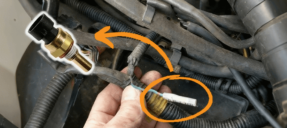
Source: fridayparts.com
What Is a Coolant Temperature Sensor Connector?
The coolant temperature sensor connector is the electrical plug that connects the engine coolant temperature sensor to the vehicle wiring harness. On many modern vehicles, the engine control module uses the sensor signal to determine coolant temperature and help control functions such as fuel delivery, ignition strategy, cooling-fan operation, and emissions-related systems.
The connector itself normally contains a plastic housing, terminals, a locking mechanism, and wires leading into the engine harness. Some applications use a short replacement harness section called a pigtail rather than a connector housing alone.
A connector problem can interrupt the electrical signal even when the coolant temperature sensor is functioning correctly. Corrosion, loose terminal tension, broken locks, heat damage, and wire fatigue can all create intermittent or permanent circuit faults.
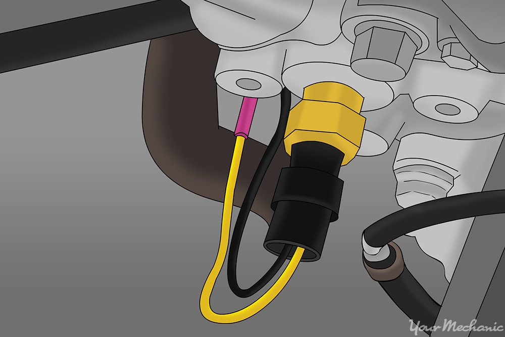
Source: YourMechanic
Connector housing
The plastic body holds the terminals in the correct positions and locks onto the sensor.
Electrical terminals
The metal terminals establish the electrical connection between the sensor and vehicle wiring.
Pigtail wires
A pigtail is a short section of replacement wiring with a connector already attached, commonly used when the original connector or nearby wiring is damaged.
Locking mechanism
The primary and, on some connectors, secondary locks prevent the connector or terminals from backing out during engine vibration.
When Should the Connector Be Replaced?
Replace the connector when inspection confirms physical or electrical damage that cannot be reliably corrected by cleaning or terminal repair. Examples include a broken connector lock that cannot secure the sensor, melted plastic, badly corroded terminals, loose terminal tension, or damaged wires immediately behind the connector.
If only dirt or light oxidation is present and the terminals remain mechanically sound, cleaning may be sufficient. If a terminal has lost its retention or contact tension, replacing the affected terminal or the complete pigtail may be more appropriate.
Broken locking tab
The connector will not remain securely attached to the coolant temperature sensor.
Corroded terminals
Corrosion can increase electrical resistance or cause an intermittent connection.
Melted housing
Heat damage can prevent the terminals from remaining correctly positioned.
Damaged wiring
Broken, stretched, rubbed-through, or chemically damaged wires near the connector can require a pigtail repair.
Tools and Parts You Need Before Starting
Gather the correct replacement connector or pigtail and the tools required for the vehicle before cutting the original wiring. The exact tools depend on the connector design and the manufacturer’s repair procedure.
A basic repair may require a digital multimeter, wire strippers designed for automotive wiring, a suitable terminal or crimping tool, heat-shrink tubing or approved sealed splice materials, electrical terminal tools, side cutters, and protective gloves and eye protection.
Do not choose a connector solely because it looks similar. Confirm the application, terminal arrangement, wire gauge, connector keying, locking features, and any special terminal plating or sealing requirements.
Source: Pelican Parts
Replacement connector or pigtail
Use the correct application-specific connector and terminals for the vehicle.
Digital multimeter
Use it to check continuity, circuit integrity, and electrical values specified by the vehicle service information.
Automotive wire repair tools
Use appropriate stripping, crimping, and terminal-removal tools rather than crushing terminals with general-purpose pliers.
Heat-shrink or sealed splice material
Use the type specified or accepted by the vehicle manufacturer to protect repaired conductors from moisture and contamination.
Safety equipment
Wear eye protection and gloves, and keep the engine fully cool before opening or disturbing components in the cooling system.
Check the Wiring Diagram First
Before cutting any wire, identify each connector cavity and the circuit associated with it. Do not assume that two wires with similar colors perform the same function. Wire colors and terminal arrangements vary among manufacturers and engine configurations.
Photograph the original connector from several angles and record the wire-to-terminal positions. If the replacement pigtail uses different wire colors, transfer the wires according to terminal position and the wiring diagram rather than color alone.
Record terminal positions
Mark the original connector cavities before disconnecting or cutting the harness.
Check wire size
The replacement wire should be appropriate for the circuit and compatible with the approved repair method.
Confirm terminal type
Some connectors use specialized terminals, seals, secondary locks, or plated contacts that require specific repair parts.
How to Replace a Coolant Temperature Sensor Connector
The safest general method is to replace the connector or pigtail without disturbing the coolant temperature sensor unless the sensor itself also needs replacement. Work with the engine cold, follow the vehicle’s electrical service precautions, and keep the repair sequence organized so each wire returns to the correct circuit.
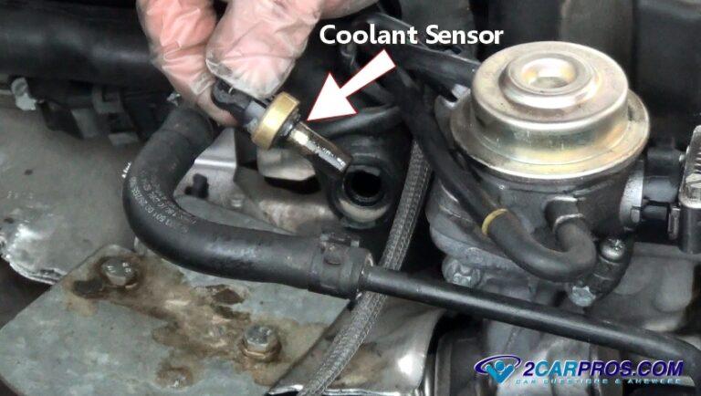
Source: 2CarPros
Step 1: Let the engine cool completely
Do not open a pressurized cooling system or remove a sensor from a hot engine. Wait until the engine and coolant have cooled sufficiently for service.
Step 2: Identify the correct connector
Compare the replacement connector with the original for terminal count, keying, locking features, wire positions, seals, and application compatibility.
Step 3: Disconnect electrical power when required
Follow the vehicle service manual for battery-disconnection requirements and any memory or electronic-system precautions.
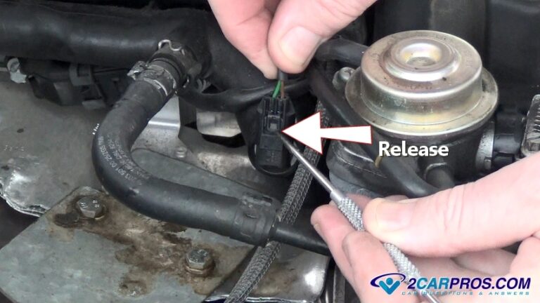
Step 4: Release the old connector
Press or release the locking tab correctly and pull the connector housing from the sensor. Do not pull on the wires to remove the connector.
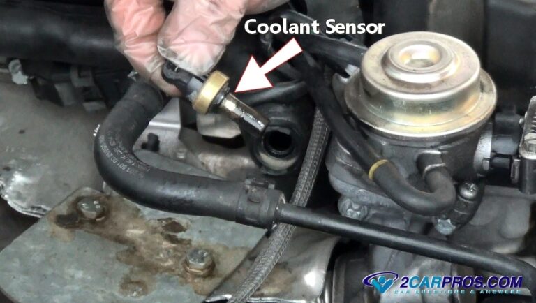
Step 5: Inspect the sensor and terminals
Look for corrosion, coolant contamination, bent terminals, damaged terminal locks, broken plastic, and evidence of overheating before proceeding.
Step 6: Document the wire positions
Photograph and label the connector cavity positions. If the pigtail has multiple wires, document the original arrangement before cutting.
Step 7: Cut and repair one wire at a time
Separate the repair points so the wires cannot be accidentally crossed. Preserve sufficient original harness length for a sound splice.
Step 8: Prepare the conductors
Strip only the amount required by the approved splice or terminal. Avoid nicking or cutting individual conductor strands.
Step 9: Make the approved splice
Use the connector manufacturer’s or vehicle manufacturer’s specified crimp, splice, seal, and heat-shrink procedure. Do not substitute an unapproved repair method merely because it is convenient.
Step 10: Seal and support the repair
Protect the splice from moisture and contamination and route the repaired harness so it cannot contact hot exhaust components, moving parts, or sharp edges.
Step 11: Connect the new pigtail
Push the connector onto the coolant temperature sensor until the locking mechanism engages. A properly seated connector should not pull off with a light verification tug.
Step 12: Restore power and inspect
Reconnect the battery if it was disconnected, inspect the harness again, and check that no wiring is stretched or trapped.
Step 13: Verify the circuit
Use the appropriate scan-tool and multimeter checks specified for the vehicle. Look for plausible coolant temperature data and any returning diagnostic trouble codes.
Why You Should Cut One Wire at a Time
Cutting one conductor at a time greatly reduces the chance of swapping circuit positions. This is especially useful when the replacement pigtail uses different wire colors from the factory harness.
For a two-wire coolant temperature sensor circuit, the wires may represent different portions of the sensor circuit, and the correct circuit identification still depends on the vehicle’s wiring diagram. Never rely on the assumption that polarity or wire color is identical across vehicles.
Mark the wires
Use temporary labels or tape to identify each original circuit before cutting.
Stagger splice locations
Where permitted by the repair procedure, stagger multiple splices so the repaired harness does not develop one large rigid bundle.
Protect the harness
Restore loom, tape, clips, and other approved harness protection after testing.
Crimping Versus Soldering
Do not assume that soldering is automatically the best automotive wiring repair. Many vehicle manufacturers specify particular crimp connectors, terminal tools, sealing sleeves, or splice procedures. Follow the service information for the vehicle and the connector repair system.
A correctly executed sealed crimp can provide both mechanical retention and electrical continuity. Whatever method is specified, the finished repair should be mechanically secure, electrically sound, properly insulated, and protected from the conditions present in the engine compartment.
Use the specified splice
Manufacturer repair procedures take precedence over a generic wiring technique.
Avoid loose connections
A splice that can be pulled apart or has poor conductor engagement can create an intermittent fault.
Keep moisture out
The repair should be sealed appropriately for an engine-compartment environment.
How to Test the Connector After Replacement
A connector replacement is not complete until the electrical circuit and sensor signal have been verified. The exact voltage, resistance, terminal identification, and acceptable limits are vehicle-specific, so use the service information for the exact application.
Start with a visual inspection. Confirm that the connector is fully seated, terminals are not pushed backward, seals are correctly positioned, and the repaired wires are not under tension. Then perform the electrical checks required for the vehicle.
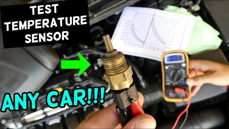
Source: YouTube > rehma6b0
Check connector engagement
Verify that the locking mechanism is fully engaged and the connector cannot easily separate from the sensor.
Inspect terminal position
Look through the connector where possible to confirm that terminals are seated evenly and none has backed out.
Check circuit continuity
Use the wiring diagram and specified test procedure to verify the circuit between the sensor connector and the control module.
Check for unwanted shorts
Where specified, verify that the circuit is not unintentionally shorted to ground or another circuit.
Check sensor signal
Use a scan tool or other specified test method to confirm that coolant temperature data is plausible.
What a Healthy Repair Should Look Like
The connector should remain firmly attached to the sensor, the wires should have no exposed conductor, and the repaired harness should have enough slack to accommodate normal engine movement without being stretched. The scan tool should report coolant temperature that is reasonable for the engine’s actual condition.
On a cold engine that has been sitting long enough to reach ambient temperature, coolant temperature data should generally be consistent with other relevant temperature measurements rather than showing an obviously implausible value. During warm-up, the reading should change in a manner consistent with the vehicle’s operating conditions.
No intermittent connection
The signal should remain stable when the harness is gently inspected and the engine operates normally.
No returning circuit fault
A repaired connector should not immediately reproduce an open-circuit, short-circuit, or implausible-signal fault.
No physical interference
The repaired wiring should remain clear of belts, fans, exhaust components, and sharp edges.
Common Problems After Replacing the Connector
If the original symptoms remain after installing a new connector, do not assume the new connector is defective. The fault may be elsewhere in the circuit or may have been misdiagnosed before the repair.
Factory diagnostic procedures commonly distinguish among connector damage, wiring opens or shorts, sensor faults, and control-module faults. Work through those possibilities systematically rather than replacing additional components at random.
Source: www.youtube.com > TRQ
The fault code returns immediately
Recheck terminal positions, connector engagement, circuit continuity, power or reference voltage, ground or return circuit, and the sensor itself according to the vehicle procedure.
The engine still shows an implausible temperature
Check the sensor and circuit rather than assuming the connector repair solved the entire problem.
The connector will not lock
Confirm that the replacement connector is the correct part and that the sensor’s mating section is not damaged.
Check coolant temperature data and diagnostic codes because the control module may use the ECT signal for engine-management decisions.
Connector Replacement Did Not Fix the Problem
If the replacement connector is correctly installed but the fault remains, test the complete circuit. A damaged wire farther along the harness can produce the same symptoms as a damaged connector. A defective coolant temperature sensor can also remain the root cause.
Some manufacturer diagnostic procedures check connector condition first, then circuit resistance or voltage, wiring continuity, and the sensor before considering a control-module problem. That sequence helps avoid unnecessarily replacing expensive electronic components.
Recheck the repair
Inspect every splice, terminal, wire position, lock, seal, and connection before expanding the diagnosis.
Test the entire circuit
Check the wiring between the sensor connector and the relevant control-module connector using the correct diagram.
Test the sensor
Compare sensor resistance or signal behavior with the vehicle manufacturer’s specifications.
Common Mistakes to Avoid
Most connector-repair failures come from incorrect identification, poor terminal handling, inadequate sealing, or failure to verify the circuit afterward. Taking a few additional minutes to document the original wiring can prevent a much longer diagnostic process.
Source: freepik.com
Working on a hot engine
Hot coolant and pressurized cooling systems can cause severe burns. Let the engine cool before working around the sensor or cooling system.
Pulling on the wires
Pulling the harness instead of releasing the connector lock can damage terminals or break conductors.
Guessing wire positions
Wire colors are not a substitute for the vehicle wiring diagram and connector cavity identification.
Using the wrong connector
A connector that physically fits may still have incorrect terminals, seals, keying, or circuit configuration.
Leaving the splice unsealed
Engine-compartment moisture and contamination can damage an inadequately protected repair.
Routing the harness incorrectly
A repaired wire can fail again if it contacts exhaust components, moving parts, sharp brackets, or areas of excessive heat.
Replacing the sensor unnecessarily
A connector or wiring fault can mimic a failed sensor, so test the circuit before replacing additional components.
When Professional Repair Is the Better Choice
Consider professional diagnosis when the wiring diagram is unavailable, the harness has extensive damage, multiple control-module circuits are affected, the connector uses specialized terminals that you cannot service correctly, or the vehicle has persistent faults after a connector replacement.
A professional technician is also appropriate when the repair requires access to complex harness sections, control-module connectors, or manufacturer-specific terminal repair equipment. A poor electrical repair can create intermittent faults that are substantially harder to diagnose later.
Extensive harness damage
Multiple damaged wires or harness sections may require a broader repair than a simple pigtail replacement.
Unclear circuit identification
Do not cut the harness when you cannot positively identify the connector cavities and circuits.
Persistent diagnostic faults
If the fault remains after a verified connector repair, further circuit-level diagnosis may be necessary.
How Long Does a Coolant Temperature Sensor Connector Replacement Take?
A simple connector pigtail replacement can be a relatively short wiring repair when the sensor is accessible and the harness has no additional damage. The actual time varies considerably with the vehicle’s engine layout, connector location, harness routing, corrosion, access, and required testing.
Do not use a generic time estimate to decide whether a repair is complete. The quality of the electrical connection, correct terminal placement, proper sealing, secure harness routing, and successful circuit verification matter more than finishing quickly.
Source: detroitchinatown.org
Easy access
A connector positioned near the top of the engine with visible wiring is generally easier to inspect and repair.
Restricted access
Sensors located beneath intake components or near other engine hardware may require additional removal steps.
Corrosion
Severely corroded terminals or wires can turn a connector replacement into a broader harness repair.
Diagnostic complexity
A persistent fault after connector replacement requires additional electrical testing before more parts are replaced.
Do You Have to Replace the Coolant Temperature Sensor Too?
No. A damaged connector does not automatically mean the coolant temperature sensor is defective. If testing shows that the sensor is within its specified operating range and the connector or wiring is the source of the fault, the sensor may not need replacement.
If the sensor is contaminated, damaged, out of specification, or otherwise confirmed faulty, replacing the sensor at the same time may make sense. Follow the vehicle-specific procedure for sensor removal, sealing, torque, coolant loss, and cooling-system refill.
Connector fault only
Repair or replace the connector while retaining a sensor that passes the required tests.
Sensor and connector faults
Replace both components when both have been independently identified as defective.
Uncertain diagnosis
Perform additional circuit and sensor testing before purchasing more replacement parts.
Safety and Final Inspection
Cooling-system and engine-compartment repairs require attention to both thermal and electrical hazards. Never remove a coolant temperature sensor or open a pressurized cooling system while the engine is hot. Coolant can be extremely hot and may be expelled under pressure.
After the connector repair, make sure all electrical connections, harness retainers, engine covers, air-intake components, and cooling-system components removed during access are correctly reinstalled. If coolant was lost during related sensor work, refill and bleed the system according to the vehicle manufacturer’s procedure.
Before driving, inspect for coolant leaks and verify the engine coolant temperature signal. If the engine overheats, the coolant level falls, a warning light returns, or the temperature reading is clearly implausible, stop troubleshooting by guesswork and diagnose the underlying system.
Source: www.youtube.com
Coolant leaks
Inspect the sensor area and any disturbed cooling-system connections before operating the vehicle normally.
Harness clearance
Confirm that repaired wiring is secured away from fans, belts, exhaust components, and sharp edges.
Diagnostic verification
Confirm that the original fault does not return and that the coolant temperature signal is plausible.
Cooling-system condition
If coolant was lost, restore the correct level and follow the specified air-bleeding procedure.
Signs the Repair Was Successful
A successful connector repair leaves the connector securely locked, the harness properly supported, and the electrical circuit operating within the vehicle’s specified parameters. The engine control module should receive a plausible coolant temperature signal, and the original connector-related fault should not return.
The final check should focus on function rather than appearance alone. A neat-looking splice can still have poor electrical continuity, while a correctly completed repair should withstand normal engine vibration and temperature changes.
Secure connection
The connector remains firmly attached to the coolant temperature sensor.
Correct signal
Scan-tool data or the specified electrical test confirms a plausible sensor signal.
No active circuit fault
The relevant diagnostic fault does not return under the conditions that originally triggered it.
Frequently Asked Questions
Q
Can I replace the coolant temperature sensor connector without replacing the sensor?
Yes. If testing shows that the sensor works correctly and the connector or nearby wiring is damaged, you can generally repair or replace the connector without replacing the sensor. The connector should be replaced with the correct application-specific part and wired according to the vehicle’s circuit diagram.
Q
How do I know if the coolant temperature sensor connector is bad?
Look for broken locking tabs, melted plastic, corrosion, loose terminals, pushed-back terminals, damaged seals, or broken wires. Electrical testing may also reveal an open circuit, excessive resistance, missing reference voltage, or another condition outside the manufacturer’s specifications. A diagnostic trouble code by itself does not prove that the connector is defective.
Q
Can a bad coolant temperature sensor connector cause poor engine performance?
Yes. If the connector causes the engine control module to receive an incorrect or intermittent coolant temperature signal, engine-management calculations can be affected. Symptoms depend on the vehicle and the exact failure, so the connector, wiring, and sensor should be tested rather than assuming the connector is the sole cause.
Q
Should I solder the wires when replacing an ECT sensor connector?
Not automatically. Use the splice and terminal repair method specified by the vehicle or component manufacturer. Some applications use sealed crimp-style repairs or specialized terminals. The objective is a mechanically secure, electrically reliable, properly sealed repair that is appropriate for the vehicle’s wiring system.
Q
Do I need to drain coolant to replace the connector?
Usually, replacing only the electrical connector does not require removing the coolant temperature sensor, so coolant draining may not be necessary. If the sensor itself must be removed, coolant may escape depending on its location. Always work with the engine cold and follow the vehicle-specific service procedure.
✦ Wrapping Up
Conclusion
Replacing a coolant temperature sensor connector is primarily an electrical wiring repair, not simply a matter of unplugging one connector and plugging in another. The most important steps are confirming the fault, identifying the correct replacement pigtail, preserving the original terminal positions, making approved sealed splices, and verifying the completed circuit.
Because coolant temperature sensor circuits vary between vehicles, the manufacturer’s wiring diagram and repair specifications should determine terminal identification, test values, splice methods, and any special procedures. If the connector repair does not resolve the fault, continue with circuit and sensor testing rather than replacing additional parts without evidence.
💡 Key Takeaway
Start with a cold engine and a confirmed diagnosis, document every connector cavity before cutting the harness, replace the connector using the vehicle-approved wiring repair method, secure and seal the harness, and verify the sensor signal before driving the vehicle normally.
Ethan Brooks is an automotive writer at Auto News 7, covering car news, vehicle maintenance, new model updates, recalls, and practical buying guides. He focuses on clear, useful information that helps drivers understand their vehicles and make better ownership decisions.
Learn how to install a coolant temperature sensor safely. Follow this step-by-step guide for removal, installation, coolant refill, leak checks, and troubleshooting.
Learn how to check an engine coolant temperature sensor with a multimeter or OBD-II scanner. Follow safe testing steps, resistance checks, symptoms, and troubleshooting tips.
Learn how to test a coolant temperature sensor with a multimeter or scan tool. Follow safe steps to check resistance, voltage, wiring, and sensor accuracy.
Learn how to remove a coolant temperature sensor safely. Follow this step-by-step guide for locating the sensor, disconnecting the wiring, draining coolant, removing the sensor, and checking for leaks.
Learn how to replace a coolant temperature sensor safely, including tools, sensor removal, installation, coolant refill, bleeding, testing, and common mistakes.