You can check an engine coolant temperature sensor by comparing its resistance or scan-tool temperature reading with the vehicle manufacturer’s specifications, while also inspecting the sensor connector and wiring.
For vehicles sold and operated in the United States, the engine coolant temperature sensor, commonly called the ECT sensor, is an important input to the engine control module. The module uses coolant temperature information to help control fuel delivery, ignition timing, emissions-related functions, and, on some vehicles, cooling-fan operation. A faulty reading can contribute to poor fuel economy, hard starting, drivability problems, or a check-engine light.
The most reliable way to test an ECT sensor depends on the vehicle. An OBD-II scan tool can show the temperature reported to the engine computer, while a digital multimeter can measure sensor resistance on many conventional thermistor-type sensors. Because resistance specifications vary substantially by vehicle and sensor design, do not use a generic resistance value as a pass-or-fail standard. Use the service information for the exact year, make, model, engine, and sensor.
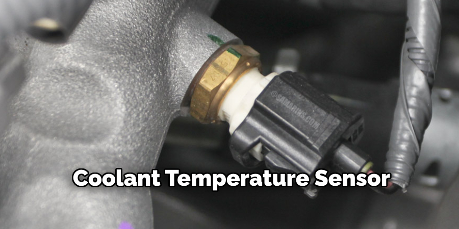
Source: ricksfreeautorepairadvice.com
What Does an Engine Coolant Temperature Sensor Do?
An engine coolant temperature sensor measures coolant temperature and sends an electrical signal to the engine control module. The computer uses that information to adjust engine-management functions according to operating temperature. Depending on vehicle design, the temperature information may also be used by the instrument cluster or cooling-fan control system.
Many ECT sensors use a thermistor whose electrical resistance changes as temperature changes. On common negative-temperature-coefficient designs, resistance decreases as temperature rises. The exact resistance curve is vehicle-specific, which is why a sensor should be evaluated against the manufacturer’s specifications rather than a universal number.
The ECT sensor is different from the coolant itself, the thermostat, and the coolant-temperature gauge. These components interact, but a temperature problem does not automatically mean the sensor is defective.
Source: i.ytimg.com
ECT
Engine coolant temperature sensor. It measures coolant temperature for the vehicle’s control systems.
ECM or ECU
The engine control module or engine control unit that interprets sensor information and controls engine functions.
Thermostat
A mechanical temperature-control component that regulates coolant flow. A thermostat problem can imitate some symptoms of an ECT problem.
OBD-II
The standardized diagnostic system used on modern U.S.-market vehicles to communicate with the vehicle’s electronic control modules and retrieve diagnostic information.
Signs That an Engine Coolant Temperature Sensor May Be Faulty
An ECT sensor or its circuit may be worth testing when the vehicle develops temperature-related engine-management symptoms or stores an ECT-related diagnostic trouble code. Common symptoms can include difficult starting, unstable idle, poor fuel economy, unusual temperature-gauge behavior, or an illuminated check-engine light.
These symptoms are not proof that the sensor itself has failed. Similar problems can result from low coolant, air trapped in the cooling system, a thermostat that does not regulate correctly, damaged wiring, connector corrosion, cooling-fan faults, or other engine-management problems.
Diagnostic trouble codes can narrow the investigation. Common ECT-related OBD-II codes include P0115 for an ECT circuit malfunction, P0116 for range or performance, P0117 for low input, and P0118 for high input. The exact diagnostic strategy and code interpretation can vary by vehicle.
Source: 2carpros.com
Temperature reading seems implausible
The scan-tool coolant temperature may be dramatically inconsistent with the engine’s actual temperature or ambient conditions.
Hard starting or poor running
An incorrect temperature signal can affect engine-management decisions, particularly during cold operation.
Check-engine light
An ECT circuit or performance problem may trigger a diagnostic trouble code.
Unusual temperature behavior
A gauge that behaves abnormally can justify further diagnosis, but the thermostat, wiring, coolant level, or gauge system may also be responsible.
What You Need Before Testing the ECT Sensor
Gather the tools appropriate for your vehicle before beginning. At minimum, you may need a digital multimeter, the manufacturer’s resistance or voltage specifications, basic hand tools for access, and appropriate personal protective equipment. An OBD-II scan tool is especially useful on modern vehicles because it allows you to compare the temperature reported by the ECT circuit with the vehicle’s actual operating conditions.
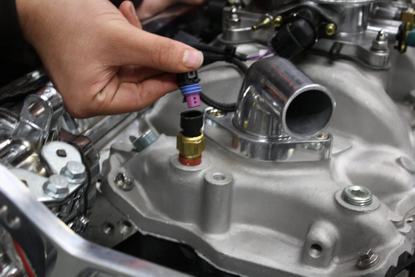
The exact location and connector design vary by vehicle. The sensor may be installed in the engine cylinder head, intake manifold, coolant outlet, thermostat housing, or another coolant passage. Consult the vehicle’s service information rather than relying on a generic location.
Source: safetyfic.com
Digital multimeter
Use a meter capable of measuring resistance and, when required by the service procedure, DC voltage.
OBD-II scanner
Useful for reading diagnostic trouble codes and viewing live coolant-temperature data from the engine control module.
Vehicle-specific specifications
You need the correct resistance, voltage, connector, and testing procedure for the exact vehicle.
Safety equipment
Wear suitable eye protection and keep hands, clothing, and tools away from moving belts, fans, and hot engine components.
Safety Before You Touch the Sensor
Work on a stable, parked vehicle with the engine switched off unless a specific diagnostic step requires the engine to run. Keep clear of electric cooling fans because some vehicles can command the fans on automatically. Most importantly, never open a pressurized radiator or coolant reservoir cap while the engine is hot. Hot coolant can cause serious burns.
If the vehicle has recently overheated, allow it to cool completely before opening the cooling system. If you see steam, a major coolant leak, or rapidly rising temperature, stop the diagnostic process and address the cooling-system hazard first.
How to Check an Engine Coolant Temperature Sensor With an OBD-II Scanner
Using an OBD-II scanner is often the quickest non-invasive way to evaluate whether the ECT reading makes sense. The key is to compare the scan-tool data with known conditions rather than assuming a particular temperature is correct for every vehicle.
A cold-soak comparison is particularly useful. After the vehicle has been parked long enough for the engine to reach ambient temperature, the ECT value should generally be plausible relative to the surrounding temperature. A reading that is dramatically implausible can point toward a sensor, connector, wiring, reference-voltage, or control-module problem. The manufacturer’s diagnostic procedure should determine the exact threshold for the vehicle.
Source: i.ytimg.com
1. Connect the scanner
Plug the OBD-II scanner into the vehicle’s diagnostic connector according to the scanner and vehicle instructions.
2. Read stored codes
Look for ECT-related diagnostic trouble codes such as P0115, P0116, P0117, or P0118, while remembering that a code identifies a circuit or performance problem rather than automatically proving the sensor is bad.
3. Check live ECT data
View the coolant temperature parameter with the engine cold and compare the reading with the actual conditions.
4. Observe warm-up
If the service information provides expected behavior, monitor the ECT value as the engine warms. An implausible, erratic, or unchanging value requires further diagnosis.
5. Verify before replacing
Inspect the sensor connector and wiring and perform the specified electrical tests before installing a replacement sensor.
What a Bad Scan-Tool Reading Can Mean
An implausible scan-tool temperature does not necessarily mean the ECT sensor itself is defective. An open circuit, short circuit, corroded connector, damaged wire, poor electrical connection, or control-module issue can alter the signal. A thermostat problem can also cause an engine to warm differently from what the driver expects even when the sensor is reporting accurately.
Use the vehicle’s wiring diagram and diagnostic procedure to distinguish a sensor fault from a circuit fault. This prevents replacing a functioning sensor when the actual problem is elsewhere.
Reading too low or too high
Investigate the sensor signal, reference circuit, ground or return path, wiring, connector, and sensor according to the manufacturer’s procedure.
Reading changes erratically
Inspect the connector and harness for loose terminals, corrosion, damaged insulation, or intermittent connections.
Reading warms slowly
Consider thermostat operation, coolant circulation, ambient conditions, and other cooling-system factors before blaming the ECT sensor.
How to Test an Engine Coolant Temperature Sensor With a Multimeter
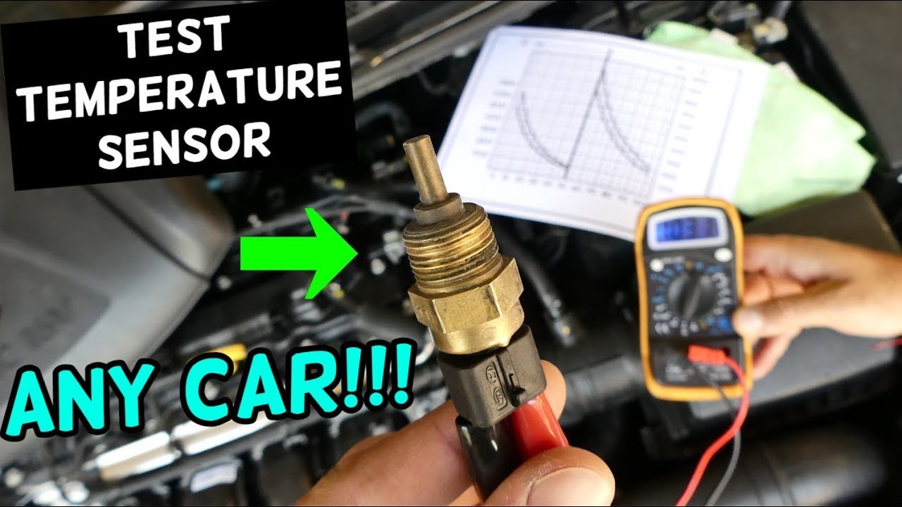
A multimeter can test many conventional ECT sensors by measuring resistance across the sensor terminals. Because the sensor’s resistance is temperature-dependent, the measurement must be compared with the manufacturer’s resistance-versus-temperature chart or specified test values.
Do not judge the sensor using a generic rule such as a fixed number of ohms. Two different sensors can have substantially different specifications. Even on the same vehicle, the required test conditions can differ by engine and model year.
Source: samarins.com
1. Let the engine cool
Begin with a cool engine unless the service procedure specifically calls for another test temperature. Avoid opening a pressurized cooling system while hot.
2. Locate the sensor
Use vehicle-specific service information to identify the ECT sensor and its electrical connector.
3. Inspect the connector
Look for corrosion, bent or pushed-back terminals, damaged locking tabs, contamination, and loose connections.
4. Disconnect the sensor
Switch the ignition off and disconnect the connector using the manufacturer’s recommended procedure. Do not pull on the wires.
5. Set the multimeter to resistance
Select the appropriate ohms range and place the probes on the sensor terminals specified by the service information.
6. Record the resistance
Measure the resistance at the known sensor temperature and compare it with the manufacturer’s specification.
7. Check temperature response if required
If the service procedure calls for multiple temperature points, measure resistance as the sensor changes temperature and compare every result with the specified resistance curve.
8. Test the circuit separately
If the sensor resistance is within specification, test the wiring, reference voltage, ground or return circuit, and connector according to the wiring diagram.
How to Interpret Resistance Measurements
For a typical negative-temperature-coefficient thermistor, resistance decreases as temperature increases. A sensor that remains electrically open, shows a short circuit, or fails to change resistance in the manner specified by the manufacturer can indicate a defective sensor. However, the exact pass-fail limits must come from the vehicle’s service information.
A useful diagnostic comparison is to measure the sensor at a known temperature and compare the result directly with the factory chart. If the measured value is outside the specified range, the sensor is suspect. If it is within range, continue testing the circuit rather than replacing the sensor automatically.
Open circuit
A meter may display OL or another indication of infinite resistance. Verify the specification and test procedure before concluding that the sensor has failed.
Short circuit
Resistance close to zero can indicate an internal short, but the acceptable value depends on the exact sensor design.
Correct resistance
A resistance value within the specified range at the specified temperature does not prove the entire ECT circuit is good; wiring and connector checks may still be required.
Wrong temperature reference
A resistance measurement without a known or controlled sensor temperature is difficult to interpret because thermistor resistance changes with temperature.
Check the ECT Sensor Wiring and Connector Before Replacing It
If the sensor measurement appears normal but the vehicle still reports an ECT fault, inspect the electrical circuit. The sensor can be healthy while the connector or wiring prevents its signal from reaching the engine control module correctly.
Look closely at the connector terminals and wiring near the sensor. Heat, vibration, coolant contamination, corrosion, previous repairs, and mechanical damage can create intermittent or high-resistance connections. Follow the vehicle’s wiring diagram for continuity, voltage, and circuit tests rather than applying a generic pinout.
Source: i0.wp.com
Connector corrosion
Corrosion or contamination can increase electrical resistance or interrupt the signal.
Damaged wiring
Broken, rubbed-through, stretched, or heat-damaged wires can cause intermittent or permanent sensor faults.
Loose terminals
A terminal that does not grip its mating pin correctly can create an intermittent ECT signal.
Incorrect pin identification
Do not probe an unknown terminal based on wire color alone. Use the vehicle-specific wiring diagram.
Why the Wiring Test Matters
Diagnostic trouble codes such as P0117 and P0118 describe abnormal ECT circuit signals, not necessarily a failed sensor. Treat the code as a direction for diagnosis. A circuit problem can produce the same apparent symptom as a defective sensor.
If the sensor resistance matches the factory specification but the scan-tool value is incorrect, the circuit between the sensor and control module deserves particular attention. Professional diagnostic equipment may be needed for difficult intermittent faults.
ECT Sensor Test Results: What Should You Do Next?
The next repair step depends on which part of the system failed. A sensor that is outside its specified resistance range should generally be replaced according to the vehicle manufacturer’s procedure. A sensor that tests correctly but has an incorrect scan-tool reading points toward further circuit or control-system diagnosis.
Do not overlook the cooling system itself. Low coolant, trapped air, a faulty thermostat, a cooling-fan problem, or restricted coolant flow can produce temperature symptoms even when the ECT sensor is functioning correctly.
Source: 2carpros.com
Sensor fails resistance test
Confirm the test conditions and specification, then replace the sensor if the manufacturer’s procedure identifies it as defective.
Sensor passes but code remains
Inspect wiring, connector terminals, reference or return circuits, and control-module inputs according to the service procedure.
ECT data looks normal but engine overheats
Investigate the thermostat, coolant level, radiator, water pump, cooling fans, air pockets, and other cooling-system components.
Engine stays unusually cool
Consider thermostat operation and other cooling-system causes rather than automatically replacing the ECT sensor.
Fault is intermittent
Inspect connectors and harness routing carefully and use live data or manufacturer-directed circuit tests to reproduce the problem.
When You Should Stop DIY Diagnosis
Get professional help when the engine is overheating, coolant is leaking significantly, electrical testing requires procedures you cannot safely perform, or the vehicle requires manufacturer-specific diagnostic equipment. Cooling systems can contain pressurized hot coolant, and modern engine-management circuits can require precise electrical testing.
A professional diagnosis is also appropriate when multiple modules report faults, the ECT data is intermittent without an obvious wiring problem, or replacing the sensor does not resolve the original symptom.
Common Mistakes When Testing a Coolant Temperature Sensor
The most common diagnostic mistake is replacing the sensor based only on a symptom or trouble code. An ECT fault can originate in the sensor, wiring, connector, coolant system, thermostat, or control system. Testing the complete circuit produces a more reliable diagnosis.
Another mistake is using a generic resistance chart. ECT sensors do not all use the same resistance curve, so a value that is normal for one vehicle can be incorrect for another. Always identify the exact sensor and vehicle before interpreting a resistance measurement.
Source: i.ytimg.com
Opening a hot radiator
Never remove a pressurized radiator cap or coolant reservoir cap from a hot system.
Using a universal resistance value
Use the exact resistance-versus-temperature specification for the vehicle being tested.
Ignoring the connector
A damaged or corroded connector can create a sensor fault even when the sensor itself is healthy.
Confusing sensor and thermostat faults
The thermostat controls coolant flow, while the ECT sensor measures temperature. Their symptoms can overlap.
Testing without knowing temperature
Because thermistor resistance changes with temperature, an unexplained resistance reading has limited diagnostic value.
Replacing parts before confirming the fault
Use scan data, resistance measurements, wiring checks, and cooling-system observations together to identify the actual cause.
Frequently Asked Questions
Q
How do I know if my coolant temperature sensor is bad?
Test the sensor rather than relying only on symptoms. Compare its resistance at a known temperature with the manufacturer’s specification, or use an OBD-II scanner to check whether the reported coolant temperature is plausible. Also inspect the connector and wiring because an electrical fault can produce the same symptoms as a failed sensor.
Q
What resistance should an engine coolant temperature sensor have?
There is no single resistance value that applies to every ECT sensor. The correct value depends on the sensor design and its temperature. Use the resistance-versus-temperature chart or test specification for the exact vehicle, engine, and sensor.
Q
Can I test an ECT sensor without removing it?
Yes. An OBD-II scanner can often show the coolant temperature being reported to the engine control module without removing the sensor. Depending on the vehicle, electrical tests can also be performed at the connector. Follow the manufacturer’s test procedure because connector access and circuit design vary.
Q
Can a bad thermostat cause the same symptoms as a bad coolant temperature sensor?
Yes. A thermostat that is stuck open can cause an engine to warm slowly or remain cooler than expected, while a thermostat or cooling-system fault can also create temperature-related symptoms. If the ECT sensor reports a plausible temperature, investigate coolant level, thermostat operation, coolant circulation, and cooling fans before replacing the sensor.
Q
What does P0117 or P0118 mean?
P0117 generally indicates a low-input problem in the engine coolant temperature sensor circuit, while P0118 generally indicates a high-input problem. These codes identify an abnormal circuit signal and do not by themselves prove that the ECT sensor has failed. The sensor, connector, wiring, power or reference circuit, and control module may need to be tested.
✦ Wrapping Up
Conclusion
The best way to check an engine coolant temperature sensor is to combine scan-tool data, a vehicle-specific electrical test, and a visual inspection of the sensor and its circuit. An OBD-II scanner can reveal whether the temperature reported to the engine computer makes sense, while a multimeter can verify sensor resistance when the manufacturer provides the appropriate test specifications.
Avoid replacing an ECT sensor solely because the vehicle has a temperature-related symptom or an ECT diagnostic trouble code. Check the connector, wiring, coolant level, thermostat, and other cooling-system components as appropriate. If the engine is overheating or the cooling system is pressurized and hot, prioritize safety and allow the system to cool before continuing.
💡 Key Takeaway
Start with a cold-engine scan-tool reading and visual inspection, then test ECT sensor resistance against the exact manufacturer specification. If the sensor passes, continue with wiring and cooling-system diagnosis instead of replacing the part automatically.
Ethan Brooks is an automotive writer at Auto News 7, covering car news, vehicle maintenance, new model updates, recalls, and practical buying guides. He focuses on clear, useful information that helps drivers understand their vehicles and make better ownership decisions.
Learn how to remove crankshaft position sensor safely and correctly. Follow step-by-step instructions, tools needed, troubleshooting tips, and common mistakes to avoid.
Learn how to replace camshaft position sensor bank 1 with a clear step-by-step process, required tools, troubleshooting tips, and safety advice for DIY vehicle owners in the USA.
Learn whether spark plugs can cause a knock sensor code, how ignition problems affect engine knock detection, common symptoms, diagnosis steps, and repair options.
Learn what causes a knock sensor to go bad, the most common failure reasons, warning signs, diagnostic tips, and how to prevent expensive engine problems.
Learn when to replace a crankshaft position sensor, how to recognize failure symptoms, diagnose the problem, and avoid replacing a good sensor unnecessarily.